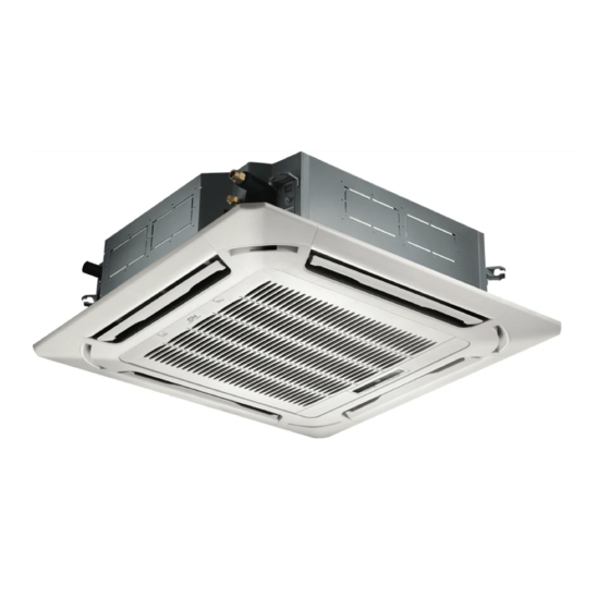
Cooper & Hunter SOPHIA CH-09MSPHCT-230VI Installation Manual
Multi-zone ductless inverter split air conditioner with heat pump cassette type indoor unit
Hide thumbs
Also See for SOPHIA CH-09MSPHCT-230VI:
- Owner's manual (17 pages) ,
- Owner's manual & installation manual (52 pages)
Advertisement
Table of Contents
SOPHIA
M UL TI-ZONE
DUCTLESS INVERTER
SPLIT AIR CONDITIONER
WITH HEAT PUMP
CASSETTE TYPE
INSTALLATION MANUAL
INDOOR UNIT
Models:
CH-09MSPHCT-230VI
CH-12MSPHCT-230VI
CH-18MSPHCT-230VI
CH-24MSPHCT-230VI
IMPORTANT NOTE:
Read this manual carefully before
•
installing or operating your new air
conditioning unit. Make sure to save
this manual for future reference.
This manual only describes the installation of
•
outdoor unit. When installing the indoor unit,
refer to the installation manual of indoor unit.
If you are using this as a MULTI unit, please refer to the installation & operation manuals that accompany the outdoor unit.
Advertisement
Table of Contents

Related Manuals for Cooper & Hunter SOPHIA CH-09MSPHCT-230VI


Summary of Contents for Cooper & Hunter SOPHIA CH-09MSPHCT-230VI
- Page 1 SOPHIA M UL TI-ZONE DUCTLESS INVERTER SPLIT AIR CONDITIONER WITH HEAT PUMP CASSETTE TYPE INSTALLATION MANUAL INDOOR UNIT Models: CH-09MSPHCT-230VI CH-12MSPHCT-230VI CH-18MSPHCT-230VI CH-24MSPHCT-230VI IMPORTANT NOTE: Read this manual carefully before • installing or operating your new air conditioning unit. Make sure to save this manual for future reference.
-
Page 2: Table Of Contents
Install strictly according to these installation instructions. CONTENTS Page If installation is defective, water leakage, electrical shock, and fire will result............PRECAUTIONS ......1 ............2 INSTALLATION INFORMATION When installing the unit in a small room, take measures to keep ...................3 ACCESSORIES refrigerant concentration from exceeding allowable safety limits... -
Page 3: Installation Information
When there are inflammable materials or gas nearby If the refrigerant leaks during installation, ventilate the area immediately. Toxic gas may be produced if the refrigerant When acid or alkaline liquid is evaporating comes into contact with fire. When other special conditions exist The temperature of the refrigerant circuit will be high, so keep the interconnection cable away from the copper tube. -
Page 4: Accessories
ACCESSORIES For the following items, take special care during construction and check after installation is finished. Ensure that the following accessories are included with your unit: Mark √ when finished Is the indoor unit fixed firmly? The unit may drop, vibrate, or make noise. Is the gas leak test finished? It may result in insufficient cooling or heating. -
Page 5: Indoor Unit Installation
INDOOR UNIT INSTALLATION Selecting an installation site When the conditions in the ceiling exceed 30 C/86 F and a relative humidity of 80%, or when fresh air is inducted into the ceiling, an 1000/39.4 in 1000/39.4 in additional insulation is required (min. 10 mm/0.4 in thickness, polyethylene foam). - Page 6 Where applicable, create the ceiling opening that is Preparations before installation necessary for installation (for existing ceilings) Relation of ceiling opening to unit and suspension bolt - From the side of the opening to the casing outlet, implement the refrigerant and drain piping and wiring for the remote control position (unnecessary for the wireless type).
- Page 7 4) Check if the unit is horizontally level Install the indoor unit - Do not install the unit tilted. The indoor unit is equipped with a When installing optional accessories, read the installation built-in drain pump and float switch. (If the unit is tilted against manual for optional accessories.
-
Page 8: Outdoor Unit Installation
Figure of body size OUTDOOR UNIT INSTALLATION Precautions for selecting the location 1) Choose a place solid enough to bear the weight and vibration of the unit, where operation noise will not be amplified. 2) Choose a location where the hot air discharged from the unit or the operation noise will not be a nuisance to neighbors. - Page 9 2.4 Outdoor unit installation 2.3 Installation guidelines When a wall or other obstacle is in the path of the outdoor unit 1) Installing the outdoor unit inlet or outlet airflow, follow the installation guidelines below. When installing the outdoor unit, refer to "Precautions for For any of the below installation patterns, the wall height on the selecting the location."...
-
Page 10: Installing The Refrigerant Pipe
INSTALLING THE REFRIGERANT PIPE 3.1 Flaring the pipe end 1) Cut the pipe end with a pipe cutter. All field piping must be provided by a licensed refrigeration 2) Remove burrs with the cut surface facing downward so that the technician and must comply with the relevant local and chips do not enter the pipe. - Page 11 3.4 Purging air and checking gas leakage 3.3 Installation of the throttle (for some models) When piping work is completed, purge the air and check for gas leakage. WARNING Do not mix any substance other than the specified refrigerant into the refrigeration cycle. When refrigerant gas leaks, ventilate the room as soon as possible.
- Page 12 Up to 15 m (49.2 ft) More than 15 m (49.2 ft) Pipe length 2) Be sure to insulate both the gas and liquid piping. Use separate thermal insulation for each. See the figure Not less than 10 min Run time Not less than 15 min below.
-
Page 13: Connecting The Drain Pipe
CONNECTING THE DRAIN PIPE 4.3 How to perform piping 4.1 Installation of drain piping 1-1.5 m Install the drain piping as shown in the figure below and take ≤300/11.8in 3-5 ft measures against condensation. Improperly rigged piping could lead to leaks and, eventually, wet furniture and belongings. 1-1.5 m 3-5 ft Unit: mm... -
Page 14: Electric Wiring Work
4.4 Testing of drain piping ELECTRIC WIRING WORK After the piping work is finished, check if drainage flows smoothy. General instructions Gradually add approximately 1 L of water through the air discharge All field wiring and components must be installed by a licensed outlet. - Page 15 How to connect wiring Remove the control box lid of the indoor unit. Remove the cover of the outdoor unit. Follow the "Wiring diagram label" attached to the indoor unit's control box lid to wire the outdoor unit, indoor unit, and remote control. Securely fix the wires with a field-supplied clamp.
-
Page 16: Installation Of The Decoration Panel
INSTALLATION OF THE DECORATION PANEL - After installing the decoration panel, ensure that there is no space between the unit body and the decoration panel. If Detach the intake grille there is, air may leak through the gap and cause dewdrop. - Slide the 2 grille hooks toward the middle of the decoration (See the figure below.) panel. -
Page 17: Test Operation
Close the intake grille and the 2 grille hooks TEST OPERATION Make sure the control box lids are closed on the indoor and outdoor units. Refer to ''For the following items, take special care during construction and check after installation is finished'' on page 3. After finishing the construction of the refrigerant piping, drain piping, and electric wiring, conduct the test operation accordingly to protect the unit. - Page 18 The design and specifications are subject to change without prior notice for product improvement. Consult with the sales agency or manufacturer for details.
Need help?
Do you have a question about the SOPHIA CH-09MSPHCT-230VI and is the answer not in the manual?
Questions and answers
Are parts available for this particular unit? In particular, I am looking for a new control board.