Table of Contents
Advertisement
Quick Links
ApplianceStor175Rv2
Performance Storage Server
User Manual
RASILIENT CONFIDENTIAL PROPRIETARY INFORMATION This document contains confidential information that is proprietary to
Rasilient or confidential information which Rasilient has legal duty to protect from disclosure. The information contained in this
document may not be disclosed without the express written permission of Rasilient Systems, Inc.
Advertisement
Table of Contents

Related Manuals for Rasilient ApplianceStor175Rv2


Summary of Contents for Rasilient ApplianceStor175Rv2
- Page 1 RASILIENT CONFIDENTIAL PROPRIETARY INFORMATION This document contains confidential information that is proprietary to Rasilient or confidential information which Rasilient has legal duty to protect from disclosure. The information contained in this document may not be disclosed without the express written permission of Rasilient Systems, Inc.
- Page 2 AS175Rv2 User Guide...
- Page 3 COPYRIGHT NOTICE All rights, including copyright, in the content of this manual are owned or controlled by RASILIENT SYSTEMS, INC. and protected by copyright. No part of this document may be photocopied, reproduced, or translated into another language without the prior consent of RASILIENT.
- Page 4 AS175Rv2 User Guide in the Purchase and Sale Agreement for this product, manufacturer and distributor of this product will not be liable whatsoever relating to the distribution and/or use of this product. In addition, manufacturer and distributor of this product hereby specifically disclaim any express or implied warranties of merchantability, fitness for a particular purpose, or non-infringement of third-party rights in connection with this product.
-
Page 5: Table Of Contents
AS175Rv2 User Guide Table of Contents About this Manual ......................8 CONVENTIONS ......................9 SAFETY SYMBOLS ...................... 10 SAFETY PRECAUTIONS ....................11 Technician Notes ......................12 Electrostatic Discharge Precautions ................... 12 Rack Warnings ........................ 13 System Warnings ......................14 REGULATORY AND INTEGRATION INFORMATION ............15 Regulatory Compliance Identification Numbers .............. - Page 6 AS175Rv2 User Guide Canadian Notice (Avis Canadien) ..................19 Power Cords ........................19 Chapter 1: Introduction ..................... 21 AUDIENCE ASSUMPTIONS ................... 22 ABOUT THIS GUIDE ....................23 PACKING CHECKLIST ....................23 SPECIFICATIONS ....................... 24 PRODUCT FEATURES ....................25 SYSTEM OVERVIEW ....................26 Front View........................
- Page 7 AS175Rv2 User Guide List of Figures Figure 1: AS175Rv2 Front Image ..............25 Figure 2: AS175Rv2 Front Panel ..............27 Figure 3: Back View of AS175Rv2 ..............28 Figure 4: Front Panel LEDs ................29 Figure 5: LAN Ports LEDs ................30 Figure 6: Management Port LEDs ..............
- Page 8 AS175Rv2 User Guide List of Tables Table 1: Safety Compliance ................16 Table 2: European Union Compliance ............... 18...
-
Page 9: About This Manual
AS175Rv2 User Guide About this Manual Conventions Safety Symbols Safety Precautions Regulatory and Integration Information... -
Page 10: Conventions
AS175Rv2 User Guide ABOUT THIS MANUAL CONVENTIONS To make sure that you perform certain tasks properly, take note of the following symbols used throughout this manual. Warning: Provides information to prevent injury in the process of completing a task. Caution: Provides information to prevent damage to the components in the process of completing a task. -
Page 11: Safety Symbols
AS175Rv2 User Guide Note: Provides tips to aid in completing a task. SAFETY SYMBOLS The following symbols are placed on some components of the system to alert the user to potential hazards. WARNING: Electric Shock Hazard - To reduce risk of injury from electric shock hazards;... -
Page 12: Safety Precautions
AS175Rv2 User Guide WARNING: Insert Network Interface Only - Any receptacle (e.g. RJ45 marked with this symbol indicates a network interface connection. To reduce the risk of electric shock, fire or damage to equipment, do not plug telephone ortelecommunications connectors into this receptacle. WARNING: This symbol, on power supplies or systems, that the equipment is supplied by multiple sources of power. -
Page 13: Technician Notes
AS175Rv2 User Guide Technician Notes ● Only authorized technicians should attempt to repair this equipment. ● Before installing this system, carefully read all the manuals included with the system. ● All repair procedures allow only module replacement. Because of the complexity of the individual boards and sub-assemblies, no one should attempt to make repairs at the component level or make modifications to any printed wiring board. -
Page 14: Rack Warnings
AS175Rv2 User Guide plastic tools and foam packaging. Avoid touching pins, leads, or circuitry. Always place drives with printed circuit board (PCB) assembly-side down. Grasp cards and boards by the edges. Hold drives by the frame. Avoid touching the solder joints or pins. ... -
Page 15: System Warnings
AS175Rv2 User Guide ambient temperature of the rack environment may be greater than room ambient. Therefore, consideration should be given to installing the equipment in an environment compatible with the maximum ambient temperature (Tma) specified by the manufacturer. Do no overload the AC power supply branch circuit that provides power to the rack. -
Page 16: Regulatory And Integration Information
AS175Rv2 User Guide operational during a power failure. The storage system must always be operated with all hot plug modules installed or slot covers in place to ensure proper cooling. Route power cords so that they will not be walked on or pinched by items places upon or against them. -
Page 17: Product Emc Compliance
AS175Rv2 User Guide Table 1: Safety Compliance IEC 60950-1:2005 +A1:2009 +A2:2013/ Safety of Information Technology Equipment EN 60950-1:2006 +A11:2009 +A1:2010 Safety of Information Technology +A12:2011 +A2:2013 Equipment Worldwide Safety approvals can be supplied upon request. Please contact your sales representative for approvals. Product EMC Compliance This product has been assembled from components that comply with the following electromagnetic compatibility (EMC) regulations. -
Page 18: Communications Commission Notice
AS175Rv2 User Guide Communications Commission Notice Part 15 of the Federal Communications Commission (FCC) Rules and Regulations has established Radio Frequency (RF) emission limits to provide an interference-free radio frequency spectrum. Many electronic devices, including computers, generate RF energy incidental to their intended function and are, therefore, covered by these rules. -
Page 19: Declaration Of Conformity For Products Marked With The Fcc Logo - United States Only
AS175Rv2 User Guide Declaration of Conformity for Products Marked with the FCC Logo - United States Only This device complies with Part 15 of the FCC Rules Operation and is subject to the following two conditions: (1) this device may not cause harmful interference that may cause undesired operation. -
Page 20: Canadian Notice (Avis Canadien)
AS175Rv2 User Guide Canadian Notice (Avis Canadien) Class A Equipment This Class A digital apparatus meets all requirements of the Canadian Interference- Causing Equipment Regulations. Cetappareil numérique de la classe A respectetoutes les exigences du Règlement sur le matériel brouilleur du Canada. Power Cords The power cord set included in the system meets the requirements for use in the country where the system was purchased. - Page 21 AS175Rv2 User Guide 1.00mm or 18AWG, and the length of the cords must be between 1.8m (6 feet) and 3.6m (12 feet). If you have questions about the type of power cord to use, contact your sales representative. The following statement applies only to rack-installed products that are GS-Marked: This equipment is not intended for use at workplaces with visual display units, in accordance with §2 of the German ordinance for workplaces with visual display units...
-
Page 22: Chapter 1: Introduction
AS175Rv2 User Guide Chapter 1: Introduction Audience Assumptions About This Guide... -
Page 23: Audience Assumptions
AS175Rv2 User Guide Packing Checklist Specifications Product Features System Overview INTRODUCTION AUDIENCE ASSUMPTIONS This manual assumes that you are a service technician or network administrator familiar with computer hardware, data storage, and network administration terminology and tasks. -
Page 24: About This Guide
AS175Rv2 User Guide ABOUT THIS GUIDE This hardware installation guide provides step by step instructions on how to prepare and install the ApplianceStor 175Rv2 Storage Server. This manual is generally organized as follows: PACKING CHECKLIST Make sure you have all the components shipped with your system. If any item is damaged or missing, please contact your sales representative for replacement. -
Page 25: Specifications
AS175Rv2 User Guide SPECIFICATIONS The table below is the technical specification for the AS175RV2Rv2 Table 5: Specifications 2x 3rd Generation Intel Xeon Scalable T4, T400 (Not available with RAID) Memory Up to 1024 GB DDR4-3200 ECC RDIMM Expansion Slot 3x PCIe Gen4 x16 Storage 2x 240/480/960 GB SSD for OS 4x 3.5”HDD (not available w/ GPU) -
Page 26: Product Features
AS175Rv2 User Guide Weight Max 42 lbs/19 kg 1+1 Redundant, 100-127Vac/ 200-240Vac, Power 12A/10A (for each inlet), 50/60Hz Watts 1600 Watts Operating Temperature 10?C - 35?C PRODUCT FEATURES This chapter describes the features of this AS175RV2. It covers each module and the module’s features and specifications. -
Page 27: System Overview
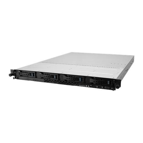
AS175Rv2 User Guide SYSTEM OVERVIEW The AS175RV2R integrates VMS and storage in a simple to use, high-performance video surveillance storage solution. It is optimized for Video Surveillance applications and delivers the performance required for the most demanding megapixel installations. Powerful Server and storage system, built around dual high-performance Intel®... -
Page 28: Front View
AS175Rv2 User Guide Rasilient provides a complete physical security solution. All necessary components are offered, including high-performance recording, viewing/monitoring and administration servers, and high-performance storage Front View The front of the AS175RV2 allows easy access to the 4 hot plug drive canisters. Each drive canister has a status LED located to the right of the release handle. -
Page 29: System Led Information
AS175Rv2 User Guide Figure 3: Back View of AS175Rv2 System LED Information This system is equipped with LED indicators for all major components of the system. These LEDs provide visual cues to the status of each of these components. -
Page 30: Figure 4: Front Panel Leds
AS175Rv2 User Guide Front Panel LEDs Figure 4: Front Panel LEDs... -
Page 31: Figure 5: Lan Ports Leds
AS175Rv2 User Guide LAN Port (RJ-45) LEDs Figure 5: LAN Ports LEDs Dedicated Management LAN port (DM_LAN1) LED indications Figure 6: Management Port LEDs HDD status LED... -
Page 32: Figure 7: Hdd Status Leds
AS175Rv2 User Guide Figure 7: HDD Status LEDs... -
Page 33: Chapter 2: Hardware Installation
AS175Rv2 User Guide Chapter 2: Hardware Installation Hard Disk Drives Power Supply Modules Mounting the System onto a Rack... -
Page 34: Hard Disk Drives
AS175Rv2 User Guide HARDWARE INSTALLATION HARD DISK DRIVES The system supports four hot-swap SATA/SAS hard disk drives. The hard disk drive installed on the drive tray connects to the motherboard SATA/SAS ports via the SATA/SAS backplane. To install a 3.5” hot-swap SATA/SAS HDD: Push the spring lock to the right (A) then pull the tray lever outward (B) to release the drive tray. -
Page 35: Figure 8: Hdd Installation
AS175Rv2 User Guide Figure 8: HDD Installation To remove a 3.5” hot-swap SATA/SAS HDD: Firmly hold the tray lever and pull the drive tray out of the bay. -
Page 36: Power Supply Modules
AS175Rv2 User Guide Figure 9: HDD Removal POWER SUPPLY MODULES The AS175RV2 contains two 1600 watt power supply modules to provide redundant power for the entire enclosure. One power supply provides enough power to boot up and run a fully loaded system. The second power supply serves as a backup in the event of a system failure. -
Page 37: To Replace A Failed Redundant Power Supply Module
AS175Rv2 User Guide To remove a power supply, follow the figure below. To insert the power supply reverse the steps. The redundant power supply module is hot pluggable. To replace a failed redundant power supply module: 1. Lift up the power supply module lever. Module lever 2. -
Page 38: Figure 10: As175Rv2 Psu Insert / Removal
AS175Rv2 User Guide 3. Prepare the replacement power supply module. 4. Insert the replacement power supply module into the chassis then push it inwards until the latch locks into place. Figure 10: AS175Rv2 PSU Insert / Removal Before you remove or install the power supply module from the AS175RV2, disconnect the power supply cords. -
Page 39: Mounting The System Onto A Rack
AS175Rv2 User Guide MOUNTING THE SYSTEM ONTO A RACK Rail kit installation The tool less design of the rail kit allows you to easily install the rack rails into the server rack without the need for additional tools. The kit also comes with a metal stopping bracket that can be installed to provide additional support and stability to the server. -
Page 40: Installing The Tool-Less Rack Rail
AS175Rv2 User Guide Installing the tool-less rack rail To install the tool-less rack rails into the rack: 1. Secure the two fixing latches to the two sides of the server using the set of latch screws. 2. Select a desired space and place the appropriate rack rail (left and right) on opposite positions on the rack. - Page 41 AS175Rv2 User Guide A 1U space consists of three square mounting holes with two thin lips on the top and the bottom. 3. Secure the rail components to the rail using the bundled screws. 4. Press the spring lock then insert the studs into the selected square mounting holes on the rack post.
- Page 42 AS175Rv2 User Guide 5. Press the spring lock on the other end of rail then insert the stud into the mounting hole on the rack post. Extend the rack rail, if necessary. 6. (Optional) Use the rail screw and rail washer that comes with the kit to secure the rack rail to the rack post.
-
Page 43: Rail Kit Dimensions
AS175Rv2 User Guide 9. Lift the server chassis and insert into the rack rail. Ensure that the rack rail cabinet and the rack posts are stable and standing firmly on a level surface. Rail kit dimensions 43.6mm 900mm 43.6mm 589mm Figure 12: Rail Kit Dimensions...
Need help?
Do you have a question about the ApplianceStor175Rv2 and is the answer not in the manual?
Questions and answers