Table of Contents
Advertisement
Quick Links
Advertisement
Table of Contents

Related Manuals for Rasilient ApplianceStor 75


Summary of Contents for Rasilient ApplianceStor 75
- Page 1 ApplianceStor 75 Performance Storage Server User Manual...
- Page 2 All rights, including copyright, in the content of this manual are owned or controlled by RASILIENT and protected by copyright. No part of this document may be photocopied, reproduced, or translated into another language without the prior written consent of RASILIENT Systems, Inc.
-
Page 3: Table Of Contents
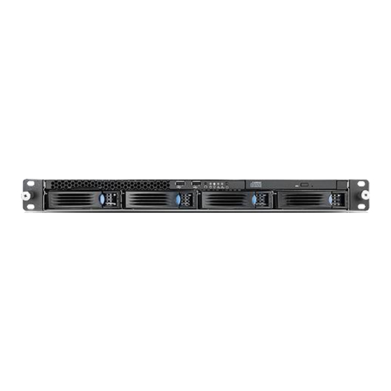
Contents About This Manual ..........................2 Conventions ............................2 Safety Symbols ........................... 3 Safety Precautions..........................4 Regulatory and Integration Information ....................6 Regulatory Compliance Identification Numbers ................6 Product Regulatory Compliance ..................... 6 Power Cords ........................... 8 Introduction ..........................1-1 Audience Assumptions ...................... - Page 4 List of Figures Figure 1 -1: AS75 .......................... 1-3 Figure 2 -1:AS75 Motherboard Rear I/O ..................2-9 Figure 2 -2: AS75 Front I/O ......................2-10...
- Page 5 List of Tables Table i European Union Safety Requirements ................7 Table 1 -1 Introduction of the Manual ..................1-1 Table 1 -2 Packing Checklist ...................... 1-1 Table 1 -3 Specifications ......................1-2...
-
Page 6: About This Manual
About This Manual Conventions Safety Symbols Safety Precautions Regulatory and Integration Information... - Page 7 About This Manual Conventions To make sure that you perform certain tasks properly, take note of the following symbols used throughout this manual. Provides Information to prevent injury in the process of completing a Warning: task. Provides Information to prevent damage to the components in the Caution: process of completing a task.
-
Page 8: Safety Symbols
Safety Symbols The following symbols are placed on some components of the system to alert the user to potential hazards, WARNING: Electric Shock Hazard – To reduce risk of injury from electric shock hazards, do not open this component. WARNING: Contains No User or Field Serviceable Parts – To reduce the risk of injury from electric shock hazards, do not open this component. -
Page 9: Safety Precautions
Safety Precautions Technician Notes Only authorized technicians should attempt to repair this equipment. Before installing this system, carefully read all the manuals included with the system. All repair procedures allow only module replacement. Because of the complexity of the individual boards and sub-assemblies, no one should attempt to make repairs at the component level or make modifications to any printed wiring board. - Page 10 To reduce the risk of electric shock or damage to the equipment, do not disable the power cord grounding plug. The grounding plug is an important safety feature. Ensure the power cord is inserted into a grounded electrical outlet that is easily accessible at all times.
-
Page 11: Regulatory And Integration Information
Regulatory and Integration Information Regulatory Compliance Identification Numbers For the purpose of regulatory compliance certifications and identification, this system is assigned a serial number. This system serial number can be found on the product label, along with the required approval markings and information. When requesting certification information for this product, always refer to this serial number. - Page 12 digital device, pursuant to Part 15 of the FCC Rules. These limits are designed to provide reasonable protection against harmful interference when the equipment is operated in a commercial environment. This equipment generates, uses, and can radiate radio frequency energy and, if not installed and used in accordance with the instructions, may cause harmful interference to radio communications.
-
Page 13: Power Cords
Power Cords The power cord set included in the system meets the requirements for use in the country where the system was purchased. If this system is to be used in another country, contact your sales representative to purchase a power cord that is approved for use in that country. The power cord must be rated for the product and for the voltage and current marked on the product's electrical ratings label. -
Page 14: Introduction
Chapter 1 Introduction Audience Assumptions About This Guide Packing Checklist Specifications System Overview... - Page 15 1 Introduction 1.1 Audience Assumptions This manual assumes that you are a service technician or network administrator familiar with computer hardware, data storage and network administration terminology and tasks. 1.2 About this Guide AS75 comes with appropriate hardware installed. User only needs to configure IP addresses, install appropriate VMS software to administer and view the cameras.
-
Page 16: Specifications
1.4 Specifications The table below is the technical specification for the AS75. Table 1 -3 Specifications Height: 1.7" / 43.5mm Dimensions Width: 16.9" / 430mm Depth: 26" / 660mm Weight Max-weight: 42 lbs / 19 kg ±5% ... -
Page 17: System Overview
1.5 System Overview The ApplianceStor75 Rack mount integrates VMS (Video Management Software) and storage into a simple to use, high performance video surveillance storage server solution. This eliminates the cost of a separate VMS server, significantly reducing cabling as well as the nightmare of integrating VMS, OS, commodity server and storage. -
Page 18: Reliable
ECC memory. The AS75R offers high performance and bandwidth connectivity to meet the requirements of the most demanding megapixel camera applications. The AS75R has unmatched LAN connectivity with four GbE ports and an additional port that is dedicated to management for a total of five GbE LAN ports. With the AS75R video surveillance appliance's flexible LAN connectivity and its impressive power, it can meet the requirements of the most demanding megapixel camera applications. -
Page 19: Open
1.11 Open Purpose built open platformto integrate Video Management Software . We have prequalified all major supported OS and VMS providers. We continually add more to ensure the widest possible certification coverage. 1.12 Video Surveillance Class Video Surveillance class drives are designed for video storage to deliver reliable 24x7 operations and optimized for low-power consumption, quiet operation, smooth video streaming, high reliability and high capacity. -
Page 20: Manageable
1.17 Manageable Very easy to manage with optional remote management. Web-based, GUI-driven iKVM upgrade kit provides full control of server functions with dedicated hotkeys and remote server screen. Virtual media-over-LAN helps share local devices with target servers, enabling fast troubleshooting. AS75 User Manual... -
Page 21: System Specification
1.18 System Specification Core Technology CPU Type Dual Intel Xeon E5-2620 v4 Broadwell (2.1Ghz) Socket 2 x Socket LGA2011-3 Core Logic Intel® C612 PCH Chipset Bench Mark/Clock speed 19377/2.1 GHz Memory size 16GB (expandable up to 64GB) Memory type DDR4 2133 ECC RDIMM Video Storage Performance Up to 120Mbps /15MBps internal and 720Mbps / 90MBps with PS5000... - Page 22 Compliance Safety US/Canada (UL1950-CSA950) Europe (CE, EN55022 compliance to EU Directive 89/366/EEC& TUV) US (FCC , CFR47 Part 15, Class A) Europe (CE, EN55022 class A & EN55024) Australia (C-TICK), Taiwan (BSMI) Physical Characteristics Dimensions (in./mm) 26" x 16.9" x 1.7" / 660 x 430 x 43.5 Weight 42lbs./19Kg26"...
-
Page 23: Component Identification
2 Component Identification; Motherboard rear I/O Following diagram shows the location of all the rear I/O modules on AS75 motherboard. Figure 2 -1:AS75 Motherboard Rear I/O AS75 User Manual... -
Page 24: Front I/O
2.2 Front I/O AS75 Front I/O are as shown below: Figure 2 -2: AS75 Front I/O 2.3 Power Supply Power supply is located in the rear of the case. The switch and power plug is shown in the figure below: AS75 User Manual 2-10...
Need help?
Do you have a question about the ApplianceStor 75 and is the answer not in the manual?
Questions and answers