Table of Contents
Advertisement
Quick Links
ApplianceStor212RS
Enterprise Grade Recording Server
User Manual
RASILIENT CONFIDENTIAL PROPRIETARY INFORMATION This document contains confidential information that is proprietary to
Rasilient or confidential information which Rasilient has legal duty to protect from disclosure. The information contained in this
document may not be disclosed without the express written permission of Rasilient Systems, Inc.
Advertisement
Table of Contents

Related Manuals for Rasilient ApplianceStor212RS


Summary of Contents for Rasilient ApplianceStor212RS
- Page 1 RASILIENT CONFIDENTIAL PROPRIETARY INFORMATION This document contains confidential information that is proprietary to Rasilient or confidential information which Rasilient has legal duty to protect from disclosure. The information contained in this document may not be disclosed without the express written permission of Rasilient Systems, Inc.
- Page 2 AS212RS User Guide...
- Page 3 COPYRIGHT NOTICE All rights, including copyright, in the content of this manual are owned or controlled by RASILIENT SYSTEMS, INC. and protected by copyright. No part of this document may be photocopied, reproduced, or translated into another language without the prior consent of RASILIENT.
- Page 4 AS212RS User Guide a particular purpose, or non-infringement of third-party rights in connection with this product. Manufacturer of this product has the right to change specifications and product descriptions at any time without notice.
-
Page 5: Table Of Contents
AS212RS User Guide Table of Contents About this Manual ......................8 CONVENTIONS ......................9 SAFETY SYMBOLS ...................... 10 SAFETY PRECAUTIONS ....................12 Technician Notes ......................12 Electrostatic Discharge Precautions ................... 12 Rack Warnings ........................ 13 System Warnings ......................14 REGULATORY AND INTEGRATION INFORMATION ............16 Regulatory Compliance Identification Numbers .............. - Page 6 AS212RS User Guide Canadian Notice (Avis Canadien) ..................19 Power Cords ........................20 Chapter 1: Introduction ..................... 21 AUDIENCE ASSUMPTIONS ................... 22 ABOUT THIS GUIDE ....................22 PACKING CHECKLIST ....................22 SPECIFICATIONS ....................... 23 PRODUCT FEATURES ....................24 SYSTEM OVERVIEW ....................26 Front View........................
- Page 7 AS212RS User Guide List of Figures Figure 1: AS212RS Front Image ..............25 Figure 2: AS212RS Front Panel ................ 27 Figure 3: Back View of AS212RS ..............28 Figure 4: Front Panel LEDs ................30 Figure 5: 1 GbE LAN Ports LEDs ............... 31 Figure 6: 10 GbE LAN Ports LEDs ..............
- Page 8 AS212RS User Guide List of Tables Table 1: Safety Compliance ................16 Table 2: European Union Compliance ............... 19...
-
Page 9: About This Manual
AS212RS User Guide About this Manual Conventions Safety Symbols Safety Precautions Regulatory and Integration Information... -
Page 10: Conventions
AS212RS User Guide ABOUT THIS MANUAL CONVENTIONS To make sure that you perform certain tasks properly, take note of the following symbols used throughout this manual. Warning: Provides information to prevent injury in the process of completing a task. Caution: Provides information to prevent damage to the components in the process of completing a task. -
Page 11: Safety Symbols
AS212RS User Guide Note: Provides tips to aid in completing a task. SAFETY SYMBOLS The following symbols are placed on some components of the system to alert the user to potential hazards. WARNING: Electric Shock Hazard - To reduce risk of injury from electric shock hazards;... - Page 12 AS212RS User Guide WARNING: Insert Network Interface Only - Any receptacle (e.g. RJ45 marked with this symbol indicates a network interface connection. To reduce the risk of electric shock, fire or damage to equipment, do not plug telephone or telecommunications connectors into this receptacle. WARNING: This symbol, on power supplies or systems, that the equipment is supplied by multiple sources of power.
-
Page 13: Safety Precautions
AS212RS User Guide SAFETY PRECAUTIONS Technician Notes ● Only authorized technicians should attempt to repair this equipment. ● Before installing this system, carefully read all the manuals included with the system. ● All repair procedures allow only module replacement. Because of the complexity of the individual boards and sub-assemblies, no one should attempt to make repairs at the component level or make modifications to any printed wiring board. -
Page 14: Rack Warnings
AS212RS User Guide arrive at a static free work area. Use a wrist strap connected to the work surface as well as properly grounded tools and equipment. Keep the area free of nonconductive materials such as ordinary plastic tools and foam packaging. ... -
Page 15: System Warnings
AS212RS User Guide unstable if more than one component is extended. Extend only one at a time. Do not stand or step on any components in the rack. If installed in a closed or multi-unit rack assembly, the operating ambient temperature of the rack environment may be greater than room ambient. - Page 16 AS212RS User Guide Protect the storage system from power fluctuations and temporary power interruptions with a regulating uninterruptible power supply (UPS). This device protects the hardware from damage caused by power surges and voltage spikes and keeps the system operational during a power failure.
-
Page 17: Regulatory And Integration Information
AS212RS User Guide REGULATORY AND INTEGRATION INFORMATION Regulatory Compliance Identification Numbers For the purpose of regulatory compliance certification and identification, this system is assigned a serial number. This system serial number can be found on the product label, along with the required approval markings and information. When requesting certification information for this product, always refer to this serial number. -
Page 18: Product Emc Compliance
AS212RS User Guide Product EMC Compliance This product has been assembled from components that comply with the following electromagnetic compatibility (EMC) regulations. FCC CFR Title 47 Part 15 Subpart B: 2019 Class A EN 55032:2015/A11:2020 , EN 55035:2017/A11:2020 , EN 61000-3-3:2013+A1:2019 , EN IEC 61000-3-2:2019 Communications Commission Notice Part 15 of the Federal Communications Commission (FCC) Rules and Regulations... -
Page 19: Class A Equipment
AS212RS User Guide have an FCC logo or FCC ID on the label. Once the class of the device is determined, refer to the following corresponding statement. Class A Equipment This equipment has been assembled with components that comply with the limits for a Class A digital device, pursuant to Part 15 of the FCC Rules. -
Page 20: Canadian Notice (Avis Canadien)
AS212RS User Guide Community. Compliance with these directives implies conformity to the following European Norms (items in brackets are the equivalent international standards): Table 2: European Union Compliance EN 55032:2015/A11:2020 Electromagnetic Interference EN 55035:2017/A11:2020 Electromagnetic Immunity EN 61000-3-2: 2014 Power Line Harmonics EN 61000-3-3: 2013 Power Line Flicker Canadian Notice (Avis Canadien) -
Page 21: Power Cords
AS212RS User Guide Power Cords The power cord set included in the system meets the requirements for use in the country where the system was purchased. If this system is to be used in another country, contact your sales representative to purchase a power cord that is approved for use in that country. -
Page 22: Chapter 1: Introduction
AS212RS User Guide Chapter 1: Introduction Audience Assumptions About This Guide Packing Checklist Specifications Product Features System Overview... -
Page 23: Audience Assumptions
AS212RS User Guide INTRODUCTION AUDIENCE ASSUMPTIONS This manual assumes that you are a service technician or network administrator familiar with computer hardware, data storage, and network administration terminology and tasks. ABOUT THIS GUIDE This hardware installation guide provides step by step instructions on how to prepare and install the AS212RS Recording Server. -
Page 24: Specifications
AS212RS User Guide Rail Kit Rail Kit for rack installation. Up to 12 hot plug 3.5” Hard Drives or SSDs Disk Drives depending on the configuration. Power Cords Two power cords SPECIFICATIONS The table below is the technical specification for the AS212RSRv2 Table 5: Specifications 2x 3rd Generation Intel Xeon Scalable T4, T400... -
Page 25: Product Features
AS212RS User Guide 6, 8, 10, 12, 14, 16,18,20,22TB SAS Drives Networking 4x GbE, optional 2x 10GbE, 1x Management Display Output 1x VGA, if T400 GPU is installed 3x mDP Input/Output 4x USB 3.2 (2x front + 2x rear) Dimensions (WxHxD) 17.7”... -
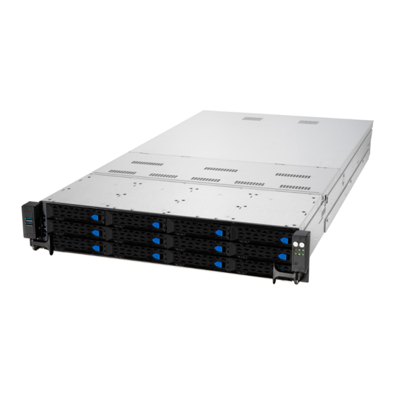
Page 26: Figure 1: As212Rs Front Image
AS212RS User Guide Figure 1: AS212RS Front Image... -
Page 27: System Overview
AS212RS User Guide SYSTEM OVERVIEW The AS212RSR integrates VMS and storage in a simple to use, high-performance video surveillance storage solution. It is optimized for Video Surveillance applications and delivers the performance required for the most demanding megapixel installations. Powerful Server and storage system, built around dual high-performance Intel®... -
Page 28: Front View
AS212RS User Guide Rasilient provides a complete physical security solution. All necessary components are offered, including high-performance recording, viewing/monitoring and administration servers, and high-performance storage Front View The front of the AS212RS allows easy access to the 12 hot plug drive canisters. Each drive canister has a status LED located to the right of the release handle. -
Page 29: Back View
AS212RS User Guide Back View The back of the AS212RS rear panel includes the expansion slots, system power socket, and rear fans. The middle part includes the I/O shield with openings for the rear panel connectors on the motherboard. Figure 3: Back View of AS212RS... -
Page 30: System Led Information
AS212RS User Guide System LED Information This system is equipped with LED indicators for all major components of the system. These LEDs provide visual cues to the status of each of these components. Front Panel LEDs... -
Page 31: Figure 4: Front Panel Leds
AS212RS User Guide Figure 4: Front Panel LEDs... -
Page 32: Figure 5: 1 Gbe Lan Ports Leds
AS212RS User Guide LAN Port (RJ-45) LEDs 1 GbE LAN port LEDs Figure 5: 1 GbE LAN Ports LEDs 10 GbE LAN port LEDs Figure 6: 10 GbE LAN Ports LEDs... -
Page 33: Figure 7: Hdd Status Leds
AS212RS User Guide HDD status LED Figure 7: HDD Status LEDs... - Page 34 AS212RS User Guide Rear Panel LEDs...
-
Page 35: Chapter 2: Hardware Installation
AS212RS User Guide Chapter 2: Hardware Installation Hard Disk Drives Power Supply Modules Mounting the System onto a Rack... -
Page 36: Hard Disk Drives
AS212RS User Guide HARDWARE INSTALLATION HARD DISK DRIVES The system supports four hot-swap SATA/SAS hard disk drives. The hard disk drive installed on the drive tray connects to the motherboard SATA/SAS ports via the SATA/SAS backplane. To install a 3.5” hot-swap SATA/SAS HDD: Push the spring lock to the right (A) then pull the tray lever outward (B) to release the drive tray. -
Page 37: Figure 8: Hdd Installation
AS212RS User Guide Figure 8: HDD Installation To remove a 3.5” hot-swap SATA/SAS HDD: Firmly hold the tray lever and pull the drive tray out of the bay. -
Page 38: Power Supply Modules
AS212RS User Guide Figure 9: HDD Removal POWER SUPPLY MODULES The AS212RS contains two 1600 watt power supply modules to provide redundant power for the entire enclosure. One power supply provides enough power to boot up and run a fully loaded system. The second power supply serves as a backup in the event of a system failure. -
Page 39: To Replace A Failed Redundant Power Supply Module
AS212RS User Guide To remove a power supply, follow the figure below. To insert the power supply reverse the steps. The redundant power supply module is hot pluggable. To replace a failed redundant power supply module: 1. Lift up the power supply module lever. Module lever 2. -
Page 40: Figure 10: As212Rs Psu Insert / Removal
AS212RS User Guide 3. Prepare the replacement power supply module. 4. Insert the replacement power supply module into the chassis then push it inwards until the latch locks into place. Figure 10: AS212RS PSU Insert / Removal Before you remove or install the power supply module from the AS212RS, disconnect the power supply cords. -
Page 41: Mounting The System Onto A Rack
AS212RS User Guide MOUNTING THE SYSTEM ONTO A RACK Rail kit installation The Rail kit package includes: Figure 11: Rail Kit Package... -
Page 42: Installing The Rack Rail
AS212RS User Guide Installing the rack rail To install the rack rails into the rack: Ensure that the rack rail cabinet and the rack posts are stable and standing firmly on a level surface. We strongly recommend that at least two able-bodied persons perform the steps described in this guide. - Page 43 AS212RS User Guide 2. Align and insert the front end of the appropriate rack rail (left and right) into the front rack post.
- Page 44 AS212RS User Guide 3. Press the spring lock on the rear end Rear rack post of the rack rail and insert the studs into the selected mounting holes on the rear rack post.
- Page 45 AS212RS User Guide 4. Slide the intermediate rail out of the outer rail until it clicks to a stop. 5. Slide the inner rail out of the intermediate rail until it clicks to a stop. Slide the white release tab outwards and remove the inner rail completely from the intermediate rail.
- Page 46 AS212RS User Guide 6. Repeat steps 2 to 5 for the other rack rail. Ensure that the installed rack rails (left and right) are aligned, secured, and stable in place. 7. Remove the three (3) screws from both left and right sides of the server system chassis, then remove the metal plate.
- Page 47 AS212RS User Guide 9. Secure the inner rails on both sides of the server system using the #6-32X4L screws.
- Page 48 AS212RS User Guide 10. Align the server system and gently insert it into the rack rails.
- Page 49 AS212RS User Guide 11. (optional) Use the M5X20L screws to secure the rack rails to the rack post. Front end of rack rail.
- Page 50 AS212RS User Guide 12. Gently push the server system until it is completely installed into the rack rail.
Need help?
Do you have a question about the ApplianceStor212RS and is the answer not in the manual?
Questions and answers