Table of Contents
Advertisement
Quick Links
MI12-00L Series
User's Manual
NO. G03-MI12-00L-F
Revision: 2.0
Release date: September 30, 2022
Trademark:
* Specifications and Information contained in this documentation are furnished for information use only, and are
subject to change at any time without notice, and should not be construed as a commitment by manufacturer.
Advertisement
Table of Contents

Related Manuals for JETWAY MI12-00L Series


Summary of Contents for JETWAY MI12-00L Series
- Page 1 MI12-00L Series User’s Manual NO. G03-MI12-00L-F Revision: 2.0 Release date: September 30, 2022 Trademark: * Specifications and Information contained in this documentation are furnished for information use only, and are subject to change at any time without notice, and should not be construed as a commitment by manufacturer.
- Page 2 Environmental Protection Announcement Do not dispose this electronic device into the trash while discarding. To minimize pollution and ensure environment protection of mother earth, please recycle.
-
Page 3: Table Of Contents
TABLE OF CONTENT ENVIRONMENTAL SAFETY INSTRUCTION ................ iv USER’S NOTICE ........................v MANUAL REVISION INFORMATION ..................v ITEM CHECKLIST ........................v CHAPTER 1 INTRODUCTION OF THE MOTHERBOARD FEATURE OF MOTHERBOARD ................1 SPECIFICATION ...................... 2 LAYOUT DIAGRAM ....................4 CHAPTER 2 HARDWARE INSTALLATION JUMPER SETTING .................... -
Page 4: Environmental Safety Instruction
Environmental Safety Instruction Avoid the dusty, humidity and temperature extremes. Do not place the product in any area where it may become wet. 0 to 60 centigrade is the suitable temperature. (The figure comes from the request of the main chipset) ... -
Page 5: User's Notice
USER’S NOTICE COPYRIGHT OF THIS MANUAL BELONGS TO THE MANUFACTURER. NO PART OF THIS MANUAL, INCLUDING THE PRODUCTS AND SOFTWARE DESCRIBED IN IT MAY BE REPRODUCED, TRANSMITTED OR TRANSLATED INTO ANY LANGUAGE IN ANY FORM OR BY ANY MEANS WITHOUT WRITTEN PERMISSION OF THE MANUFACTURER. -
Page 6: Chapter 1 Introduction Of The Motherboard
Chapter 1 Introduction of the Motherboard 1-1 Feature of Motherboard Intel ® Apollo Lake series SoC Processor, with low power consumption never denies high performance 1* SO-DIMM slot supports 1* 1866 MHz DDR3L SO-DIMM, up to 8GB C-media USB Audio ... -
Page 7: Specification
1-2 Specification Spec Description Design Mini-ITX form factor; PCB size: 17.0x17.0cm ® Intel Apollo Lake *SoC CPU *CPU model varies from different IPC options. Please consult your dealer for more information of onboard CPU. 1* DDR3L SO-DIMM slot Memory ... - Page 8 1* Front panel header 1* 9-pin USB 2.0 header COM1/2: 2* 9-pin Serial port header 1* LAN activity LED header 1* PS2 Keyboard & Mouse header 1* Front panel audio header Internal I/O 1* 10-pin GPIO header ...
-
Page 9: Layout Diagram
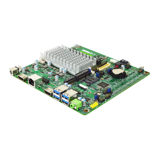
1-3 Layout Diagram Rear IO Panel Diagram: 1.0Gbps LAN1 RJ-45 LAN Port 12V DC-In USB 3.0 Ports HDMI2 Port Power Jack Line-out HDMI1 Port Warning!! The board has a 12V DC-in power connector (DCIN3) in I/O back panel and an internal 12V power connector (DCIN2). - Page 10 Motherboard Internal Diagram SYSFAN Internal 12V DC- in Connector *LAN1_LED Header DDR3L Slot (SODIMM1) Full-size Mini-PCIE Slot (MPE1) Rear IO Connector LVDS M.2 Socket 3 Slot (M2) CPUFAN SATA Power-out Connector SMBUS Header SATA III Port INVERTER USB 2.0 Ports *SIMCARD Slot FB_BUZZ Header PS/2 Keyboard &...
- Page 11 Jumper Positions: ATX_AT JMD1 JMD2...
- Page 12 Jumper Jumper Name Description JMD1 COM1 Serial Port Power Select 4-pin Block (2.54 pitch) JMD2 COM2 Serial Port Power Select 4-pin Block (2.54 pitch) MPE1 Mini-PCIE Power 3VSB / 3.3V Select 3-Pin Block (2.54 pitch) ATX_AT ATX Mode / AT Mode Select 3-Pin Block (2.54 pitch) LVDS/EDP Inverter Power 3.3V/5V/12V Select...
- Page 13 SATAPW SATA Power Connector CPUFAN CPU Fan Connector SYSFAN System Fan Connector Headers Header Name Description Front Panel Header (PWR 9-pin Block (2.54 pitch) LED/ HDD LED/Power Button /Reset) F_USB1 USB 2.0 Header 9-pin Block (2.54 pitch) COM1 RS232/422/485 Serial Port Header 9-pin Block (2.0 pitch) COM2...
-
Page 14: Chapter 2 Hardware Installation
Chapter 2 Hardware Installation 2-1 Jumper Setting (1) JMD1 (4-pin): COM1 Port Pin9 Function Select (2.54 pitch) JMD1 2-4 Closed: 3-4 Closed: 4-6 Closed: RING=RS232 12V. (2) JMD2 (4-pin): COM2 Header Pin9 Function Select (2.54 pitch) JMD2 2-4 Closed: 3-4 Closed: 4-6 Closed: RING=RS232 12V. - Page 15 (3) JP1 (3-pin): MPE1 Mini-PCIE Slot Power VCC3.3V/3VSB Select (2.54 pitch) MPE1 (4) ATX_AT (3-pin): AT/ATX Mode Select (2.54 pitch) ATX_AT *ATX Mode Selected: Press power button to power on after power input ready; AT Mode Selected: Directly power on as power input ready.
- Page 16 (5) JP4 (3-pin): LVDS / EDP Inverter Backlight VCC 5V/12V Select (2.54 pitch) 1-2 Closed: VCC=5V(Default); 2-3 Closed: VCC=12V (6) JP3 (4-pin): LVDS / EDP Panel VCC 3.3V/5V/12V Select (2.54 pitch) 2-4 Closed: 3-4 Closed: 4-6 Closed: VCC= VCC= 5V VCC= 12V 3.3V(Default);...
- Page 17 (7) JP2 (8-pin): Jumper Combo Block (2.54 pitch) Pin 1&2 of JP2 (8-pin): Case Open Message Display Function Select Pin (1-2) Close: When Case Open function pin short to GND, the Case Open function was detected. When Used, needs to enter BIOS and enable ‘Case Open Detect’ function.
- Page 18 Pin 3&4 of JP2 (8-pin): TXE Override Setting (2.54 pitch) Pin 5&6 of JP2 (8-pin): Clear CMOS (2.54 pitch)
-
Page 19: Connectors And Headers
Pin 7&8 of JP2 (8-pin): Clear ME_RTC (2.54 pitch) 2-2 Connectors and Headers 2-2-1 Connectors 1.0Gbps 12V DC-In LAN1 RJ-45 LAN Port Power Jack USB 3.0 Ports HDMI2 Port Line-out HDMI1 Port... - Page 20 (1) Rear I/O Connectors Icon Name Function 12V DC–in system power connector Power Jack For user to connect compatible power adapter to provide power supply for the system. To connect display device that support HDMI HDMI Port specification. This connector is standard RJ-45 LAN jack for Network connection.
- Page 21 (2) DCIN2 (2-pin): Internal 12V DC-in power connector DCIN2 Warning!! The board has a 12V DC-in power jack (DCIN3) in I/O back panel and an internal 12V power connector (DCIN2). User can only connect one type of compatible power supply to one of them to power the system.
- Page 22 (4) SATAPW (4-pin) : SATA Power-out Connector SATAPW (5) CPUFAN (4-pin): CPU FAN Connector CPUFAN (6) SYSFAN (4-pin): FAN Connector SYSFAN...
-
Page 23: Headers
2-2-2 Headers *Notice: The following diagrams serves as illustration purpose only. Some of the headers are only optional. In the case of any differences please refer to the model you purchased for actual specifications. (1) FP (9-pin): Front Panel Header (2.54 pitch) (2) F_USB1 (9-pin): USB 2.0 Port Header (2.54 pitch) - Page 24 (3) COM1/COM2 (9-pin): RS232 Serial Port Header (2.0 pitch) COM2 COM1 Pin NO. RS232 Pin 1 Pin 2 Pin 3 Pin 4 Pin 5 Pin 6 Pin 7 Pin 8 Pin 9...
- Page 25 (4) LAN1_LED (2-pin): LAN Activity LED Header (2.54 pitch) LAN1_LED (5) PS2KBMS (6-pin): PS/2 Keyboard & Mouse Header (2.54 pitch) Pin1 KB_DATA KB_CLK SMBUS_DA SMBUS_DA MS_CLK MS_DATA PS2KBMS...
- Page 26 (6) FP_AUDIO (9-pin): Line-Out, MIC-In Header (2.54 pitch) This header connects to Front Panel Line-out, MIC-In connector with cable. FP_AUDIO (7) GPIO (10-pin): GPIO Header (2.54 pitch) GPIO...
- Page 27 (8) SMBUS (5-pin): SMBUS Header (2.54 pitch) SMBUS FP_BUZZ (2-pin): Buzzer Header (2.54 pitch) FP_BUZZ (10) INVERTER (8-pin): LVDS Inverter Connector (2.0 pitch) Pin1 Pin No. Definition Backlight Enable INVERTER Backlight PW M Back Light LED VCC Back Light LED VCC Warning! Find Pin-1 location of the inverter and make sure that the Backlight Up SW installation direction is correct! Otherwise serious harm will occur to...
- Page 28 (11) EDP (40-pin): EDP wafer (1.25 pitch) Pin NO. Pin Define Pin NO. Pin Define Pin 1 Pin 21 *Note: Pin18/19/20 please Pin 2 Pin 22 follow the setting of JP3 Pin 3 EDP_TXN3 Pin 23 Pin 4 EDP_TXP3 Pin 24 Pin 5 Pin 25 Pin 6...
- Page 29 (12) LVDS (30-pin): 24-bit dual channel LVDS Header (2.0 pitch) LVDS Pin NO. Pin Define Pin NO. Pin Define Pin 1 E-DATAN3 Pin 2 E-DATAP3 Pin 3 E-CLKN Pin 4 E-CLKP Pin 5 E-DATAN2 Pin 6 E-DATAP2 Pin 7 E-DATAN1 Pin 8 E-DATAP1 Pin 9...
-
Page 30: Chapter 3 Introducing Bios
Chapter 3 Introducing BIOS Notice! The BIOS options in this manual are for reference only. Different configurations may lead to difference in BIOS screen and BIOS screens in manuals are usually the first BIOS version when the board is released and may be different from your purchased motherboard. -
Page 31: Bios Menu Screen
BIOS Menu Screen The following diagram show a general BIOS menu screen: Menu Bar General Help Items Current Setting Value Menu Items Function Keys... -
Page 32: Function Keys
Function Keys In the above BIOS Setup main menu of, you can see several options. We will explain these options step by step in the following pages of this chapter, but let us first see a short description of the function keys you may use here: ... -
Page 33: Memu Bars
3-5 Menu Bars There are six menu bars on top of BIOS screen: Main To change system basic configuration Advanced To change system advanced configuration Chipset To change chipset configuration Security Password settings Boot To change boot settings Save & Exit Save setting, loading and exit options. -
Page 34: Main Menu
3-6 Main Menu Main menu screen includes some basic system information. Highlight the item and then use the <+> or <-> and numerical keyboard keys to select the value you want in each item. System Date Set the date. Please use [Tab] to switch between date elements. System Time Set the time. -
Page 35: Advanced Menu
3-7 Advanced Menu OS Selection The optional settings: [Windows]; [Intel Linux]; [MSDOS]. *Note: User need to go to this item to select the OS mode before installing corresponding OS driver, otherwise problems will occur when installing the driver. Trusted Computing Press [Enter] to enable or disable ‘Security Device Support’. - Page 36 SHA256 PCR Bank Use this item to enable or disable SHA256 PCR Bank. The optional settings: [Disabled]; [Enabled]. Pending Operation Use this item to set an Operation for the Security Device.. The optional settings: [None]; [TPM Clear]. *Note: Your Computer will reboot during restart in order to change state of security device.
- Page 37 Serial Port Use this item to enable or disable serial port 2 (COMB). The optional settings are: [Disabled]; [Enabled]. When set as [Enabled], user can make further settings in the following items: Change Settings Use this item to select an optimal setting for Super IO Device. The optional settings are: [Auto];...
- Page 38 WatchDog Wake-up Timer Value User can select a value in the range of [10] to [4095] seconds when ‘WatchDog Wake- up Timer Unit’ set as [Sec]; or in the range of [1] to [4095] minutes when ‘WatchDog Wake-up Timer Unit’ set as [Min]. WatchDog Wake-up Timer Unit The optional settings are: [Sec.];...
- Page 39 A parity bit can be sent with the data bits to detect some transmission errors. The optional settings: [None]; [Even]; [Odd]; [Mark]; [Space]. [Even]: parity bit is 0 if the num of 1’s in the data bits is even; [Odd]: parity bit is 0 if num of 1’s in the data bits is odd;...
- Page 40 Redirection After BIOS POST The optional settings are: [Always Enable]; [BootLoader]. Whet [Bootloader] is selected, then Lagacy Console Redirection is disabled before booting to legacy OS. When [Always Enable] is selected, then Legacy Console is enabled for legacy OS. Default setting for this option is set to [Always Enable]. Serial Port for Out-of-Band Management/ Windows Emergency Management Services (EMS) Console Redirection...
- Page 41 Data Bits The default setting is: [8]. *This item may or may not show up, depending on different configuration. Parity The default setting is: [None]. *This item may or may not show up, depending on different configuration. Stop Bits The default setting is: [1]. *This item may or may not show up, depending on different configuration.
- Page 42 CPU Configuration Press [Enter] to view current CPU configuration and make settings for the following sub- items: VT-d Use this item to enable or disable CPU VT-d. The optional settings: [Enabled]; [Disabled]. EIST Use this item to enable or disable Intel SpeedStep. The optional settings: [Disabled];...
- Page 43 The optional settings are: [Disabled]; [Enabled]. Use this item to enable Ipv4 PXE Boot Support. When set as [Disabled], Ipv4 boot option will not be created. Ipv6 PXE Support The optional settings are: [Disabled]; [Enabled]. Use this item to enable Ipv6 PXE Boot Support. When set as [Disabled], Ipv6 boot option will not be created.
- Page 44 Use this item to enable or disable System wake on alarm event. The optional settings: [Disabled]; [Enabled]. When set as [Enabled], the following items shall appear: Wake-up Hour Use this item to select 0-23. For example enter 3 for 3am and 15 for 3pm. Wake-up Minute Use this item to select 0-59.
- Page 45 The optional settings are: [Disabled]; [Enabled]. USB Hardware Delays and Time-outs: USB Transfer Time-out Use this item to set the time-out value for control, bulk, and interrupt transfers. The optional settings are: [1 sec]; [5 sec]; [10 sec]; [20 sec]. Device Reset Time-out Use this item to set USB mass storage device start unit command time-out.
-
Page 46: Chipset Menu
3-8 Chipset Menu ► Uncore Configuration Press [Enter] to make settings for the following sub-items: GTT Size The optional settings are: [2MB]; [4MB]; [8MB]. DVMT Pre-Allocated Use this item to select DVMT 5.0 pre-allocated (fixed) graphics memory size used by the internal graphics device. - Page 47 The optional settings are: [Disabled]; [LVDS]; [eDP]. * When set as [LVDS], user can make further setting in the following sub-items: LCD Panel Type Use this item to select LCD panel used by Internal Graphics Device by selecting the appropriate setup item. The optional settings are: [800x480 1-ch 18-bit];...
- Page 48 Onboard PCIE LAN The optional settings: [Disabled]; [Enabled]. SATA Configuration Press [Enter] to make settings for the following sub-items: SATA Controller Use this item to enable or disable the Chipset SATA Controller. The Chipset SATA controller supports the 2 blank internal SATA ports (up to 3Gb/s supported per port). The optional settings are: [Enabled];...
-
Page 49: Security Menu
3-9 Security Menu Security menu allow users to change administrator password and user password settings. Administrator Password If there is no password present on system, please press [Enter] to create new administrator password. If password is present on system, please press [Enter] to verify old password then to clear/change password. - Page 50 Secure Boot Mode Set UEFI Secure Boot Mode to Standard mode or Custom mode. This change is effective after save. After reset, this mode will return to Standard mode. The optional settings are: [Standard]; [Custom]. *When set as [Custom], user can make further settings in ‘Key Management’. ...
-
Page 51: Boot Menu
3-10 Boot Menu Setup Prompt Timeout Use this item to set number of seconds to wait for setup activation key. Bootup Numlock State Use this item to select keyboard numlock state. The optional settings are: [On]; [Off]. Quiet Boot The optional settings are: [Disabled]; [Enabled]. Boot Option Priorities Boot Option #1/ Boot Option #2/ Boot Option #3 Use this item to set the system boot order. -
Page 52: Save & Exit Menu
Boot Option #1 Use this item to set the system boot order. The optional settings are: [MMC-BJTD4R]; [Disabled]. 3-11 Save & Exit Menu Save Changes and Reset This item allows user to reset the system after saving the changes. Discard Changes and Reset This item allows user to reset the system without saving any changes. - Page 53 Restore User Defaults Use this item to restore defaults to all the setup options. Boot Override The available options here are dynamically updated and make system boot to any boot option selected. Windows Boot Manager (MMC-BJTD4R) MMC-BJTD4R UEFI: Built-in EFI Shell Lauch EFI Shell from filesystem device Use this item to launch EFI shell application (shell.efi) from one of the available filesystem device.
Need help?
Do you have a question about the MI12-00L Series and is the answer not in the manual?
Questions and answers