Table of Contents
Advertisement
Quick Links
MM21 Series
User's Manual
No. G03-MM21-F
Rev: 1.0
Release date: September 29, 2022
Trademark:
* Specifications and Information contained in this documentation are furnished for information use only, and are
subject to change at any time without notice, and should not be construed as a commitment by manufacturer.
Advertisement
Table of Contents

Related Manuals for JETWAY MM21 Series


Summary of Contents for JETWAY MM21 Series
- Page 1 MM21 Series User’s Manual No. G03-MM21-F Rev: 1.0 Release date: September 29, 2022 Trademark: * Specifications and Information contained in this documentation are furnished for information use only, and are subject to change at any time without notice, and should not be construed as a commitment by manufacturer.
-
Page 2: Table Of Contents
TABLE OF CONTENT ENVIRONMENTAL SAFETY INSTRUCTION ............... iii ENVIRONMENTAL PROTECTION ANNOUCEMENT ............iii USER’S NOTICE ........................iv MANUAL REVISION INFORMATION ................... iv ITEM CHECKLIST ........................ iv CHAPTER 1 INTRODUCTION OF THE MOTHERBOARD SPECIFICATION ....................1 LAYOUT DIAGRAM ....................2 CHAPTER 2 HARDWARE INSTALLATION JUMPER SETTING .................... -
Page 3: Environmental Safety Instruction
Environmental Safety Instruction Avoid the dusty, humidity and temperature extremes. Do not place the product in any area where it may become wet. 0 to 40 centigrade is the suitable temperature. (The figure comes from the request of the main chipset) ... -
Page 4: User's Notice
USER’S NOTICE COPYRIGHT OF THIS MANUAL BELONGS TO THE MANUFACTURER. NO PART OF THIS MANUAL, INCLUDING THE PRODUCTS AND SOFTWARE DESCRIBED IN IT MAY BE REPRODUCED, TRANSMITTED OR TRANSLATED INTO ANY LANGUAGE IN ANY FORM OR BY ANY MEANS WITHOUT WRITTEN PERMISSION OF THE MANUFACTURER. -
Page 5: Chapter 1 Introduction Of The Motherboard
Chapter 1 Introduction of the Motherboard 1-1 Specification Spec Description Design Micro ATX form factor; PCB size: 24.4 x24.4 cm Chipset MM21-Q4700/Q4702 Series: Intel Q470E Chipset MM21-W4800/W4802 Series: Intel W480E Chipset Intel LGA 1200 Socket supports 10 Gen. -
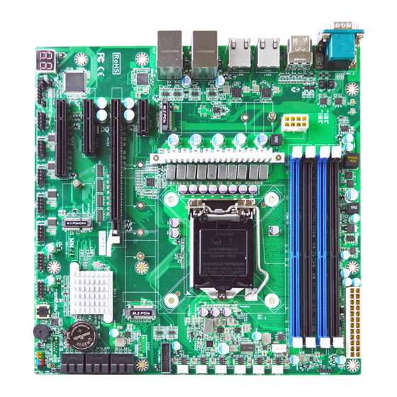
Page 6: Layout Diagram
1* CPUFAN connector & 6* SYSFAN connector 1* Front panel header 2* 9-Pin USB 2.0 headers for 4* USB 2.0 expansion ports 1* 19-Pin USB 3.2(Gen.1) header for 2* USB 3.2(Gen.1) ports 1* 8-bit GPIO header ... - Page 7 Motherboard Internal Diagram MM21-Q4700/Q4702 Series: ATX Power DDR4 Connector DIMM Slot x 4 ATX 12V Power Connector SMBUS1 Header LGA 1200 SYSFAN1 CPU Socket *Rear IO Connector SYSFAN2 (Refer to Page-2) CPUFAN1 SYSFAN3 M.2 M-Key Slot Type-2260/2280 SYSFAN4 (M2M2) SYSFAN5 M.2 M-Key Slot Type-2242/2260/2280/22110 SYSFAN6...
- Page 8 MM21-W4800/W4802 Series: ATX Power DDR4 Connector DIMM Slot x 4 ATX 12V Power Connector SMBUS1 Header LGA 1200 SYSFAN1 CPU Socket *Rear IO SYSFAN2 Connector (Refer to Page-2) CPUFAN1 SYSFAN3 M.2 M-Key Slot Type-2260/2280 SYSFAN4 (M2M2) SYSFAN5 M.2 M-Key Slot Type-2242/2260//2280/22110 SYSFAN6 (M2M1, support NVMe)
- Page 9 Motherboard Jumper Position: JAT_ATX JBAT COPEN *Note: The diagrams in the manual are mostly taken from MM21-Q4700/Q4702 series unless otherwise stated. Jumper Jumper Name Description Pitch JBAT Clear CMOS RAM Settings 3-pin Block 2.0mm JAT_ATX ATX/AT Mode Select 3-pin Block 2.54mm COPEN Case Open Message Display Detect...
- Page 10 Connectors Connector Name COM1-2 Serial Port X2 HDMI1-2 HDMI 1.4 Port X2 (Max Resolution: 4096x2160@30Hz) LAN3/LAN4 2.5GbE RJ-45 LAN Port X2 UL1/UL2 Top: 1.0GbE RJ-45 LAN Port X2 Middle & Bottom: USB 3.2(Gen.2) Port X4 ATXPWR1 ATX Type Main Power Connector ATX12V1 ATX 12V Power Connector CPUFAN1...
-
Page 11: Chapter 2 Hardware Installation
Chapter 2 Hardware Installation 2-1 Jumper Setting JBAT (3-pin): Clear CMOS RAM Settings Pitch=2.0mm 1-2 Open: Normal; 2-3 Closed: Clear CMOS. JBAT JAT_ATX (3-pin): AT Mode /ATX Mode Select Pitch=2.54mm JAT_ATX *ATX Mode Selected: Press power button to power on after power input ready; AT Mode Selected: Directly power on as power input ready. - Page 12 COPEN (2-pin): Case Open Message Display Function Pitch=2.54mm → COPEN Case Open Detection Pin1 COPEN Pin 1-2 Short: When Case open function pin short to GND, the Case open function was detected. When Used, needs to enter BIOS and enable ‘Case Open Detect’ function.
-
Page 13: Connectors And Headers
JP1 (2-pin): ME Features Select Pitch=2.0mm JP4 (2-pin): PCIe x16 & Dual PCle x8 Function Select Pitch=2.0mm JP4 PCIe x16 & Dual PCIe x8 Function Select Pin1 1-2 Open: PCIe x16 Select (Default); Pin1 1-2 Closed: Dual PCIe x8 Select. Connectors and Headers 2-2-1 Rear I/O Back Panel Connectors *Refer to Page-2 Rear IO Diagram... - Page 14 This connector is standard RJ-45 LAN jack for RJ-45 LAN Port Network connection. These two RJ-45 LAN port from UL1 and UL2 support 1.0GbE transfer rate. To connect USB keyboard, mouse or other devices compatible with USB 3.2(Gen.2) USB 3.2(Gen.2) Port specification.
-
Page 15: Motherboard Internal Connectors
2-2-2 Motherboard Internal Connectors (1) ATXPWR1 (24-pin block): Main Power Connector ATX Power Supply connector: This is a new defined 24-pins connector that usually comes with ATX case. The ATX Power Supply allows using soft power on momentary switch that connect from the front panel switch to 2-pins Power On jumper pole on the motherboard. - Page 16 (2) LAN1/LAN2 (1.0GbE) RJ-45 LAN Port ** There are two LED next to the LAN port. Please refer to the table below for the LAN port LED indications Activity/Link Speed A: Speed LED B: Activity/Link LED Status Description Status Description 10Mbps Connection No Link Green...
- Page 17 (5) CPUFAN1 (4-pin): CPU Fan Connector CPUFAN1 Control Fan Speed +12V Fan Power Pin1 (6) SYSFAN1/2/3/4/5/6 (3-pin): System Fan Connectors SYSFAN1 SYSFAN2 SYSFAN3 SYSFAN4 SYSFAN5 SYSFAN6 (7) SATA_RA1/2/3 & SATA7/8*(7-pin): SATAIII Port connector These are high-speed SATAIII ports that support 6GB/s transfer rate. *SATA7 &...
- Page 18 (8) M2M1 & M2M2 Slot: M.2 M-Key Slot M2M1 M.2 M-Key slot supports compatible type-2242/2260/2280/22110 PCIE x4 SSD modules. M2M2 M.2 M-Key slot supports compatible type-2260/2280 PCIE x2 SSD modules. M2M2 M2M1 M2M1 Slot Installation Guide: 1. Prepare compatible M.2 SSD card. Deferent type of cards has different length.
-
Page 19: Header Pin Definition
(9) Dual Channel Memory Installation: Configuration DIMM1 DIMM2 DIMM3 DIMM4 install install install install install install install install Notice! For dual channel installation, you need to install the same brand, speed, size and type memory module. It is unable to activate dual channel feature if you install one or three memory modules, or you install DIMM1 &... - Page 20 (2) FP_USB2/FP_USB3 (9-pin): USB 2.0 Port Headers Pitch=2.54mm FP_USB2 FP_USB3 (3) FP_USB1 (19-pin):USB 3.2(Gen.1) Port Header Pitch=2.0mm FP_USB1 (4) COM3/4/5/6 (9-pin): RS232 Serial Port Header Pitch=2.54mm *Note: COM3/4/5/6 ports are optional for MM21-W4800/W4802 Series. Pin6 Pin1 COM4 COM6 COM3 COM5...
- Page 21 (5) GPIO (10-pin): GPIO Port Header Pitch=2.54mm Pin1 GPIO (6) PS2KBMS (6-pin): PS/2 Keyboard & Mouse Header Pitch=2.54mm PS2KBMS (7) SMBUS1 (5-Pin): SMBUS Header Pitch=2.0mm VCC3 SMBUS1 SMBUS_ALERT- SMBUS_DATA SMBUS_DATA SMBUS_CLK Pin1...
-
Page 22: Maximum Voltage & Current Limit
2-2-4 Maximum Voltage & Current Limit Below is a list of maximum voltage & Current Limit specification for motherboard interface (including but not limited to slots, connectors, wafers and headers) for setup reference: Location Function Working Voltage Current Support COM1 Port Pin9 Function 5V/12V 500mA COM2 Port Pin9 Function... -
Page 23: Chapter 3 Introducing Bios
Chapter 3 Introducing BIOS Notice! The BIOS options in this manual are for reference only. Different configurations may lead to difference in BIOS screen and BIOS screens in manuals are usually the first BIOS version when the board is released and may be different from your purchased motherboard. Users are welcome to download the latest BIOS version form our official website. -
Page 24: Bios Menu Screen
3-2 BIOS Menu Screen The following diagram show a general BIOS menu screen: Menu Bar General Help Items Current Setting Value Menu Items Function Keys 3-3 Function Keys In the above BIOS Setup main menu of, you can see several options. We will explain these options step by step in the following pages of this chapter, but let us first see a short description of the function keys you may use here: ... -
Page 25: Menu Bars
Press 【F1】 to pop up a small help window that describes the appropriate keys to use and the possible selections for the highlighted item. To exit the Help Window, press <Esc>. 3-5 Menu Bars There are six menu bars on top of BIOS screen: Main To change system basic configuration Advanced... -
Page 26: Advanced Menu
3-7 Advanced Menu Connectivity Configuration Use this item to configure Connectivity related options. Press [Enter] to make settings for the following sub-items: CNVi present CNVi Configuration CNVi Mode This option configures Connectivity. The optional settings: [Disabled Integrated]; [Auto Detection]. [Auto Detection] means that if Discrete solution is discovered it will be enabled by default. - Page 27 [Enabled], it allows CPU to go to C states when it’s not 100% utilized. The optional settings: [Disabled]; [Enabled]. Turbo Mode Use this item to enable or disable processor Turbo Mode (requires Intel Speed Step or Intel Speed Shift to be available and enabled.) The optional settings: [Disabled];...
- Page 28 Trusted Computing Press [Enter] to make settings for the following sub-items: TPM2.0 Device Found NOTE: TPM function is optional, MM21-Q4702 & MM21-W4802 model support TPM2.0 Security Device Support Use this item to Enables or Disables BIOS support for security device. O.S. will not show security Device.
- Page 29 *Note: This function is supported when ‘ERP Support’ is set as [Disabled]. USB S3/S4 Wake-up Use this item to enable or disable USB Power after System Shutdown. The optional settings: [Disabled]; [Enabled]. *Note: This function is supported when ‘ERP Support’ is set as [Disabled]. USB S5 Power Use this item to USB Power after system shutdown support only disable ERP Function.
- Page 30 When set as [Enabled], user can make further settings in the following items: Device Settings Change Settings Use this item to select an optimal setting for Super IO Device. The optional settings: [IO=2F8h; IRQ=3;]; [IO=3F8h; IRQ=3,4,5,7,10,11;]; [IO=2F8h; IRQ=3,4,5,7,10,11;]; [IO=3E8h; IRQ=3,4,5,7,10,11;]; [IO=2E8h; IRQ=3,4,5,7,10,11;].
- Page 31 The optional settings: [IO=2E8h; IRQ=10;]; [IO=3F8h; IRQ=3,4,5,7,10,11;]; [IO=2F8h; IRQ=3,4,5,7,10,11;]; [IO=3E8h; IRQ=3,4,5,7,10,11;]; [IO=2E8h; IRQ=3,4,5,7,10,11;]; [IO=3E0h; IRQ=3,4,5,7,10,11;]; [IO=2E0h; IRQ=3,4,5,7,10,11;]. ‘Serial Port 4’ item may or may not show up, depending on different *Note: chipset. Q4700 chipset supports this item. ► Serial Port 5 Configuration Press [Enter] to make settings for the following items: Serial Port 5 Configuration Serial Port...
- Page 32 following sub-items shall appear: WatchDog Reset Timer Value User can select a value in the range of [4] to [255] seconds when ‘WatchDog Reset Timer Unit’ set as [Sec]; or in the range of [4] to [255] minutes when ‘WatchDog Reset Timer Unit’ set as [Min]. WatchDog Reset Timer Unit The optional settings: [Sec.];...
- Page 33 SYSFAN3/4/5/6 Smart Mode The optional settings: [Disabled]; [Enabled]. When set as [Enabled], the following sub-items shall appear: SYSFAN3/4/5/6 Full-Speed Temperature Use this item to set SYSFAN full speed temperature. Fan will run at full speed when above this pre-set temperature. SYSFAN3/4/5/6 Full-Speed Duty Use this item to set SYSFAN full-speed duty.
- Page 34 [Mark] and [Space]: parity do not allow for error detection. Stop Bits Stop bits indicate the end of a serial data packet. (A start bit indicates the beginning). The standard setting is 1 stop bit. Communication with slow devices may require more than 1 stop bit. The optional settings: [1];...
- Page 35 Flow Control EMS Flow control can prevent data loss from buffer overflow. When sending data, if the receiving buffers are full, a “stop” signal can be sent to stop the data flow. Once the buffers are empty, a “start” signal can be sent to re-start the flow. Hardware flow control uses two wires to send start/stop signals.
- Page 36 IPv4 PXE Support Use this item to enable IPv4 PXE boot support. When set as [Disabled], IPv4 boot support will not be available. The optional settings: [Disabled]; [Enabled]. IPv6 PXE Support Use this item to enable IPv6 PXE boot support. When set as [Disabled], IPv6 boot support will not be available.
-
Page 37: Chipset Menu
3-8 Chipset Menu System Agent (SA) Configuration Press [Enter] to make settings for the following sub-items: System Agent (SA) Configuration VT-d ► Memory Configuration Press [Enter] to view brief information for the working memory module. ► Graphics Configuration Press [Enter] to make further settings for Graphics Configuration. Graphics Configuration Primary Display Use this item to select which of IGFX/PEG Graphics device should be Primary... - Page 38 DVMT Total Gfx Mem Use this item to select DVMT5.0 Total Graphic Memory size used by the Internal Graphics Device. The optional settings: [128M]; [256M]; [MAX]. ► PEG Port Configuration Press [Enter] to make further settings for PEG port options. PEG Port Configuration PCIE2 Slot Enable Root Port...
-
Page 39: Security Menu
The optional settings: [Always On]; [Always Off]; [Former State]. *Note: The option [Always On] and [Former State] are affected by ‘ERP Support’ function. Please disable ERP to support [Always On] and [Former State] function. 3-9 Security Menu Security menu allow users to change administrator password and user password settings. - Page 40 effective after save. After reset, this mode will return to Standard mode. In Custom mode, Secure Boot Policy variables can be configured by a physically present user without full authentication. The optional settings: [Standard]; [Custom]. When set as [Custom], user can make further settings in the following items that show up: ...
-
Page 41: Boot Menu
3-10 Boot Menu Boot Configuration Setup Prompt Timeout Use this item to set number of seconds to wait for setup activation key. 65535 (0xFFFF) means indefinite waiting. Bootup NumLock State Use this item to select keyboard NumLock state. The optional setting are: [On]; [Off]. Quiet Boot The optional settings: [Disabled];... -
Page 42: Save & Exit Menu
3-11 Save & Exit Menu Save Options Save Changes and Reset This item allows user to reset the system after saving the changes. Discard Changes and Reset This item allows user to reset the system without saving any changes. Default Options Restore Defaults Use this item to restore /load default values for all the setup options.
Need help?
Do you have a question about the MM21 Series and is the answer not in the manual?
Questions and answers