Table of Contents
Advertisement
Quick Links
MI24 Series
User's Manual
NO. G03-MI24-F
Revision: 1.0
Release date: November 23, 2023
Trademark:
* Specifications and Information contained in this documentation are furnished for information use only, and are
subject to change at any time without notice, and should not be construed as a commitment by manufacturer.
Advertisement
Table of Contents

Related Manuals for JETWAY MI24 Series


Summary of Contents for JETWAY MI24 Series
- Page 1 MI24 Series User’s Manual NO. G03-MI24-F Revision: 1.0 Release date: November 23, 2023 Trademark: * Specifications and Information contained in this documentation are furnished for information use only, and are subject to change at any time without notice, and should not be construed as a commitment by manufacturer.
- Page 2 Environmental Protection Announcement Do not dispose this electronic device into the trash while discarding. To minimize pollution and ensure environment protection of mother earth, please recycle.
-
Page 3: Table Of Contents
TABLE OF CONTENT ENVIRONMENTAL SAFETY INSTRUCTION................iii USER’S NOTICE..........................iv MANUAL REVISION INFORMATION...................iv ITEM CHECKLIST..........................iv CHAPTER 1 INTRODUCTION OF THE MOTHERBOARD FEATURE OF MOTHERBOARD..................1 SPECIFICATION........................2 LAYOUT DIAGRAM.......................3 CHAPTER 2 HARDWARE INSTALLATION JUMPER SETTINGS......................8 CONNECTORS, HEADERS AND WAFERS..............12 2-2-1 REAR I/O PANEL CONNECTORS.............. -
Page 4: Environmental Safety Instruction
Environmental Safety Instruction Avoid the dusty, humidity and temperature extremes. Do not place the product in any area where it may become wet. 0 to 40 centigrade is the suitable temperature. (The temperature comes from the request of the chassis and thermal solution) ... -
Page 5: User's Notice
USER’S NOTICE COPYRIGHT OF THIS MANUAL BELONGS TO THE MANUFACTURER. NO PART OF THIS MANUAL, INCLUDING THE PRODUCTS AND SOFTWARE DESCRIBED IN IT MAY BE REPRODUCED, TRANSMITTED OR TRANSLATED INTO ANY LANGUAGE IN ANY FORM OR BY ANY MEANS WITHOUT WRITTEN PERMISSION OF THE MANUFACTURER. -
Page 6: Chapter 1 Introduction Of The Motherboard
Chapter 1 Introduction of the Motherboard 1-1 Feature of Motherboard Intel Raptor Lake-P i5-1335UE/i5-1355U SoC Processor (15W TDPs) ® 2* DDR5 4800MHz SO-DIMM up to 64GB Integrated with 2* Intel 2.5GbE LAN chips ® 2* HDMI, 1* LVDS (or 1-Lane eDP) ... -
Page 7: Specification
2* DP 1.4a from 2* USB3.2 (Gen.2) Type-C 1* LVDS/eDP * Note: MI24 series support Quad Displays Integrated with 1* Intel i225-LM & 1* Intel i225-V dual 2.5GbE PCIe LAN chips LAN Chips Support 10/100/1000/2500Mbps Ethernet data transfer rate ... -
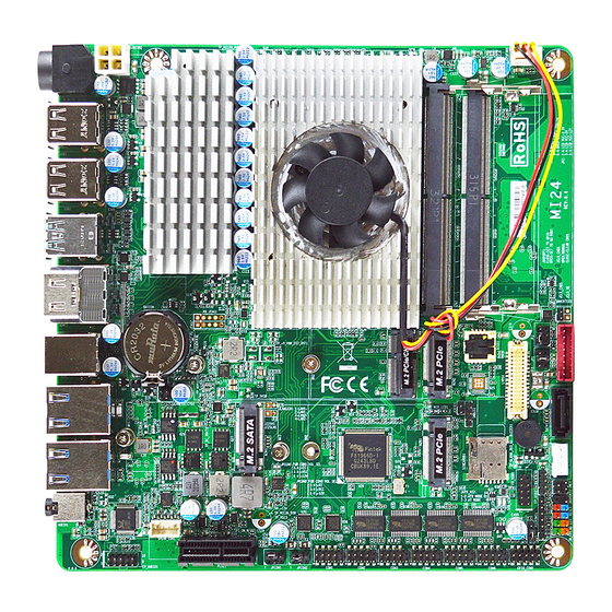
Page 8: Layout Diagram
1* Audio jack (Line-out/MIC combo) 1* 12V~24V internal ATX-type power connector (DCIN2) 1* SATA HDD power-out connector 1* CPUFAN1 connector 1* Front panel hearer 1* Front panel audio header 1* 3W 8ΩSpeaker wafer 1* LAN Activity LED header (JLANLED1) ... - Page 9 Motherboard Internal Diagram Internal ATX-Type Power Connector CPUFAN1 (DCIN2) DDR5 SODIMM Slots *Rear IO LVDS1 Connector (Refer to Page-3) M.2 E-Key Slot INVERTER1 (M2E1) M.2 M-Key Slot SATAIII Port (M2M2) (SATA1) SMBUS1 JLANLED1 M.2 B-Key Slot M.2 M-Key Slot (*M2B1) SATAPWR1 (M2M1) SPEAK_CON1...
- Page 10 Motherboard Jumper Position JCLR_CMOS JCASE1 JME1 J80PORT1 JPCOM2 JATX_AT1 JPCOM1...
- Page 11 Jumpers: Jumper Function Description Pitch JCLR_CMOS Clear CMOS RAM Settings 2-pin Block 2.0mm JPCOM1 COM1 Header Pin9 Function Select 4-pin Block 2.0mm JPCOM2 COM2 Header Pin9 Function Select 4-pin Block 2.0mm JATX_AT1 ATX Mode / AT Mode Select 3-pin Block 2.0mm JCASE1 Case Open Display Select 2-pin Block 2.0mm...
- Page 12 Headers & Wafers: Header Name Description Pitch Front Panel Header (PWR LED/ HD JW_FP1 9-pin Block 2.54mm LED/Power Button /Reset) FP_AUDIO1 Front Panel Audio Header 9-pin Block 2.0mm SPEAK_CON1 3W 8ΩAmplifier Wafer 4-pin Block 2.0mm JLANLED1 LAN Activity LED Header 4-pin Block 2.0mm FP_USB1...
-
Page 13: Chapter 2 Hardware Installation
Chapter 2 Hardware Installation 2-1 Jumper Settings JCLR_CMOS (2-pin): Clear CMOS RAM Setting JCLR_CMOS JCLR_CMOS Clear CMOS → Pin1 1-2 Open: Normal(default); Pin1 Short: Clear CMOS. JPCOM1/ JPCOM2(4-pin): COM1 /COM2 Port Pin9 Function Select JPCOM1 → COM1 Header Pin-9 VCC JPCOM2 →... - Page 14 JATX_AT1 (3-pin): AT Mode /ATX Mode Select JAT_ATX1 → ATX/AT Mode Select 1-2 Closed: ATX Mode Selected(default); JATX_AT1 2-3 Closed: AT Mode Selected. *ATX Mode Selected: Press power button to power on after power input ready; AT Mode Selected: Directly power on as power input ready. JCASE1 (2-pin): Case Open Message Display Function JCASE1 →...
- Page 15 J80PORT1 (2-pin): GPIO_CON 80 Port/GPIO Function Select J80PORT1 → GPIO/80 Function Select Pin1 1-2 Open: GPIO_CON1= 80 Port; J80PORT1 Pin1 1-2 Closed: GPIO_CON1= GPIO Port(Defaut). JME1 (2-pin): ME Features Select JME1 ME Features Select → Pin1 1-2 Open: Enable ME Features; JME1 Pin1 1-2 Closed: Disable ME Features.
- Page 16 JP1 (4-pin): LVDS Inverter BACKLIGHT VCC Select JP2 (4-pin): LVDS LCD Panel Power VCC Select *Note: Maximum current limit is 2A while using 3.3V/5V/12V working voltage *Warning! Wrong voltage setting will result in screen burn out.
-
Page 17: Connectors, Headers And Wafers
2-2 Connectors, Headers and Wafers 2-2-1 Rear I/O Panel Connectors Rear Panel Connectors 2.5GbE RJ-45 LAN Ports (LAN1: I225V) 2.5GbE USB 2.0 Ports HDMI Ports RJ-45 LAN Ports (LAN2: I225-LM) USB 3.2 (Gen.2) USB 3.2 (Gen.2) Line-Out/MIC Combo 12V~24V DC-in Ports Type-C Ports Audio Jack... - Page 18 Type-C USB 3.2 Type-C USB3.2(Gen.2) port also supports DP ALT (Gen.2) & DP 1.4a Port mode & PD 5V/3A This connector is standard RJ-45 LAN jack for Network 2.5Gbps connection which supports10/100/1000/2500 Mbps RJ-45 LAN Port Ethernet data transfer rate (*Note: 2.5Gbps is only supported with CAT 5e UTP cable).
- Page 19 (2) 2.5GbE RJ-45 Ethernet Connectors ** There are two LED next to the RJ-45 LAN port. Please refer to the table below for LAN port LED indications. For 2.5Gbps RJ-45 LAN port LED Signals: 2.5GbE RJ-45 LAN Ports (LAN1: I225V) 2.5GbE RJ-45 LAN Ports (LAN2: I225-LM)
-
Page 20: Motherboard Internal Connectors
2-2-2 Motherboard Internal Connectors (1) DCIN2 (4-pin block): Internal 12V~24V Wide-Voltage Power Connector DCIN2 Pin1 Pin No. Definition +12V~24V +12V~24V (2) CPUFAN1 (4-pin):CPU Fan Connector CPUFAN1 Pin1... - Page 21 (3) SATA1 (7-pin block):SATAIII Port connector The board comes with a SATAIII port supporting 6GB/s transfer rate. Pin No. Definition SATA1 (4) SATAPW1 (4-pin): SATA HDD Power-out Connector +12V SATAPW1 Pin1...
-
Page 22: Pin Definitions For Headers & Wafers
2-2-3 Pin Definition for Headers & Wafers (1) JW_FP1 (9-pin): Front Panel Header RSTSW PWRBTN PWR LED- HDD LED HDD LED+ PWR LED+ JW_FP1 Pin 1 (2) FP_AUDIO1 (9-pin): Line-Out, MIC-In Header This header is connected to Front Panel Line-out, MIC connector with cable. FP_AUDIO... - Page 23 (3) SPEAK_CON1 (4-pin): 3W 8ΩAmplifier Wafer Pin1 SPEAK_CON1 (4) JLANLED1 (4-pin): LAN1 & LAN2 Activity LED Header JLANLED1 Pin1 *Note: Maximum current limit is 300uA while using 3.3V working voltage.
- Page 24 (5) FP_USB1 (9-pin): USB 2.0 Port Header +DATA +DATA -DATA -DATA FP_USB1 Pin 1 (6) FP_USB2 (4-pin): USB 2.0 Port Header +DATA -DATA FP_USB2 Pin 1...
- Page 25 (7) PS2KBMS1 (6-pin): PS/2 Keyboard & Mouse Header MS_DATA MS_CLK KB_CLK KB_DATA Pin 1 PS2KBMS1 (8) SMBUS1 (4-Pin): SMBUS Header SMBUS_DATA SMBUS1 SMBUS_CLK Pin 1...
- Page 26 (9) COM1/2/3/4/5/6 (9-pin): Serial Port Header COM1/2:RS232/422/485 Serial Port; COM3/4/5/6:RS232 Serial Port Header. Pin NO. RS232 *RS422 *RS485 (COM1/2) (COM1/2) Pin 1 DATA- DATA+ Pin 2 SIN- Pin 3 Pin 4 DTR- *COM1 Pin 5 Pin 6 DSR- *COM2 COM6 COM4 Pin 7 RTS-...
- Page 27 (10) LVDS1 (30-pin): 24-bit Dual Channel LVDS Header(or 1-Lane eDP) LVDS1 Pin Define Pin NO. Pin NO. Pin Define LCD_VCC Pin 30 Pin 29 LCD_VCC LCD_VCC Pin 28 Pin 27 LCD_VCC LVDSA_DATAN0 Pin 26 Pin 25 LVDSA_DATAP0 Pin 24 Pin 23 LVDSA_DATAN1 LVDSA_DATAP1 LVDSA_DATAN2/EDP_TX1N...
-
Page 28: Maximum Voltage & Current Limit
(11) INVERTER1 (8-pin): LVDS/eDP Inverter Connector INVERTER1 Warning! Find Pin-1 location of the inverter and make sure that the installation direction is correct! Otherwise serious harm will occur to the board/display panel!! 2-3 Maximum Voltage & Current Limit Below is a list of maximum voltage & Current Limit specification for motherboard interface (including but not limited to slots, connectors and headers) for setup reference: Parts Working Voltage... -
Page 29: Chapter 3 Introducing Bios
Chapter 3 Introducing BIOS Notice! The BIOS options in this manual are for reference only. Different configurations may lead to difference in BIOS screen and BIOS screens in manuals are usually the first BIOS version when the board is released and may be different from your purchased motherboard. Users are welcome to download the latest BIOS version form our official website. -
Page 30: Bios Menu Screen
3-2 BIOS Menu Screen The following diagram show a general BIOS menu screen: Menu Bar BIOS Menu Screen General Help Items Menu Items Current Setting Value Function Keys... -
Page 31: Function Keys
3-3 Function Keys In the above BIOS Setup main menu of, you can see several options. We will explain these options step by step in the following pages of this chapter, but let us first see a short description of the function keys you may use here: ... -
Page 32: Menu Bars
3-5 Menu Bars There are six menu bars on top of BIOS screen: Main To change system basic configuration Advanced To change system advanced configuration Chipset To change chipset configuration Security Password settings Boot To change boot settings Save & Exit Save setting, loading and exit options. -
Page 33: Advanced Menu
System Date Set the date. Please use [Tab] to switch between date elements. System Time Set the time. Please use [Tab] to switch between time elements. 3-7 Advanced Menu Connectivity Configuration Press [Enter] to make settings for the following sub-item: CNVi Mode This option configures connectivity. - Page 34 The optional settings are: [Disable Integrated]; [Auto Detection] CPU Configuration Press [Enter] to view current CPU configuration and make settings for the following sub-items: CPU Configuration Efficient-Core Information Press [Enter] to view the E-Core Information. Performance-Core Information Press [Enter] to view the P-Core Information.
- Page 35 The optional settings are: [C0/C1]; [C2]; [C3]; [C6]; [C7]; [C7S]; [C8]; [C9]; [C10]; [Cpu Default]; [Auto]. Power Limit 1 Use this item to set Power Limit 1 in Milli Watts. BIOS will round to the nearest 1/8W when programming. 0 = no custom override. For 12.5W, enter 12500. Overclocking SKU: Value must be between Max and Min Power Limits (specified by PACKAGE_POWER_SKU_MSR).
- Page 36 Press [Enter] to make settings in the following sub-items: Security Device Support Use this item to enables or disables BIOS support for security device. O.S. will not show security device. TCG EFI protocol and INT1A interface will not be available. The optional settings: [Disabled];...
- Page 37 Serial Port Use this item to enable or disable serial port (COM). The optional settings: [Disabled]; [Enabled]. Change Settings Use this item to select an optimal settings for super IO device. The optional settings are: [Auto]; [IO=3F8h; IRQ=4]; [IO=2F8h; IRQ=3]; [IO=3E8h; IRQ=4];...
- Page 38 Serial Port Use this item to enable or disable serial port (COM). The optional settings: [Disabled]; [Enabled]. Change Settings Use this item to select an optimal setting for super IO device. The optional settings are: [Auto]; [IO=3F8h; IRQ=11]; [IO=2F8h; IRQ=11]; [IO=3E8h;...
- Page 39 WatchDog Reset Timer Unit The optional settings are: [Sec.]; [Min.] WatchDog Wake-up Timer Support WDT Wake-up. The optional settings are: [Disabled]; [Enabled]. When set as [Enabled], the following sub-items shall appear: WatchDog Wake-up Timer Value User can set a value in the range of [10] to [4095] seconds, or [1] to [4095] minutes.
- Page 40 [VT100]: ASCII char set; [VT100Plus]: Extends VT100 to support color, function keys, etc. [VT-UTF8]: Uses UTF8 encoding to map Unicode chars onto 1 or more bytes. Bits per second Use this item to select serial port transmission speed. The speed must be matched on the other side.
- Page 41 Recorder Mode With this mode enable only text will be sent. This is to capture Terminal data. The optional settings: [Disabled]; [Enabled]. Resolution 100x31 Use this item to enable or disable extended terminal resolution. The optional settings: [Disabled]; [Enabled]. Putty KeyPad Use this item to select Function Key and KeyPad on Putty.
- Page 42 Redirection Settings’ screen: Console Redirection Settings The settings specify how the host computer and the remote computer (which the user is using) will exchange data. Both computers should have the same or compatible settings. Press [Enter] to make settings for the following sub-items. Terminal Type EMS The optional settings: [VT100];...
- Page 43 ► PC Health Status Press [Enter] to view current hardware health status, make further settings in ‘SmartFAN Configuration’ and set value in ‘Shutdown Temperature’. ► SmartFAN Configuration Press [Enter] to make settings for SmartFAN Configuration: SmartFAN Configuration CPUFAN Smart Mode The optional settings: [Disabled];...
- Page 44 USB hardware Delays and Time-outs; USB Transfer time-out Use this item to set the time-out value for control, bulk, and interrupt transfers. The optional settings: [1 sec]; [5 sec]; [10 sec]; [20 sec]. Device reset time-out Use this item to set USB mass storage device start unit command time-out. The optional settings: [10 sec];...
- Page 45 Use this item to set number of times the presence of media will be checked. Use either +/- or numeric keys to set the value. NVMe Configuration Press [Enter] to view current NVMe Configuration. *Note: options only when NVME device is available. ►...
-
Page 46: Chipset Menu
activating this function in S4. The optional settings: [Enabled]; [Disabled]. PCIE Wake-up from S3-S5 The optional settings: [Disabled]; [Enabled]. PTT Configuration Press [Enter] to make settings for the following sub-items: PTT Capability/state TPM Device Selection The optional settings are: [dTPM]; [PTT]. Use this item to selects TPM device: PTT or dTPM. - Page 47 System Agent (SA) Configuration Press [Enter] to make settings for the following sub-items: System Agent (SA) Configuration VMD setup menu Press [Enter] to make settings for the following sub-items: Enable VMD controller Use this item to enable/disable to VMD controller The optional settings: [Disabled];...
- Page 48 [1280*800 1ch 18bit]; [1280*800 1ch 24bit]; [1366*768 1ch 18bit]; [1366*768 1ch 24bit]; [1440*900 2ch 18bit]; [1440*900 2ch 24bit]; [1280*1024 2ch 24bit]; [1680*1050 2ch 24bit]; [1920*1080 2ch 24bit]; [eDP]. Backlight Control Use this item to back light control setting The optional settings: [PWM Inverted]; [PWM Normal]. Maximum Memory Frequency Use this item to set maximum memory frequency selections in Mhz.
-
Page 49: Security Menu
Use this item to enable/disable SATA Port. The optional settings: [Disabled]; [Enabled]. Hot Plug Use this item to designate this port as Hot Pluggable. The optional settings: [Disabled]; [Enabled]. HD Audio Use this item to control detection of the HD-Audio device. Disabled= HDA will be unconditionally disabled. - Page 50 Security menu allow users to change administrator password and user password settings. Administrator Password If there is no password present on system, please press [Enter] to create new administrator password. If password is present on system, please press [Enter] to verify old password then to clear/change password.
- Page 51 This item enables expert users to modify Secure Boot Policy variables without variable authentication, which includes the following items: Vendor Keys Factory Key Provision This item is for user to install factory default Secure Boot keys after the platform reset and while the System is in Setup mode. The optional settings: [Disabled];...
-
Page 52: Boot Menu
3-10 Boot Menu Boot Configuration Setup Prompt Timeout Use this item to set number of seconds to wait for setup activation key. 65535(0xFFFF) means indefinite waiting. Bootup Numlock State Use this item to select the keyboard NumLock state. The optional settings are: [On]; [Off]. Quiet Boot Use this item to enable/disable Quiet Boot option. -
Page 53: Save & Exit Menu
Boot Option Priorities Boot Option #1 Use this item to set the system boot order. The optional settings: [UEFI: Built –in EFI Shell]; [Disabled]. Drover Option Prioritirs 3-11 Save & Exit Menu Save Changes and Reset This item allows user to reset the system after saving the changes. Discard Changes and Reset This item allows user to reset the system without saving any changes. - Page 54 Use this item to save the changes done so far as user defaults. Restore User Defaults Use this item to restore the User Defaults to all the setup options. Boot Override UEFI: Built – in EFI Shell Use this item to save configuration and reset. 3-12 MEBx Configuration locked after End0fPost...
Need help?
Do you have a question about the MI24 Series and is the answer not in the manual?
Questions and answers