Table of Contents
Advertisement
Quick Links
JMTX-ADN8 Series
User's Manual
NO.: G03-MTX-ADN8-F
Revision: 2.0
Release date: August 1, 2024
Trademark:
* Specifications and Information contained in this documentation are furnished for information use only, and are
subject to change at any time without notice, and should not be construed as a commitment by manufacturer.
Advertisement
Table of Contents

Related Manuals for JETWAY JMTX-ADN8 Series


Summary of Contents for JETWAY JMTX-ADN8 Series
- Page 1 JMTX-ADN8 Series User’s Manual NO.: G03-MTX-ADN8-F Revision: 2.0 Release date: August 1, 2024 Trademark: * Specifications and Information contained in this documentation are furnished for information use only, and are subject to change at any time without notice, and should not be construed as a commitment by manufacturer.
- Page 2 Environmental Protection Announcement Do not dispose this electronic device into the trash while discarding. To minimize pollution and ensure environment protection of mother earth, please recycle.
-
Page 3: Table Of Contents
TABLE OF CONTENT ENVIRONMENTAL SAFETY INSTRUCTION ................iv USER’S NOTICE ........................v MANUAL REVISION INFORMATION ..................v ITEM CHECKLIST ........................v CHAPTER 1 INTRODUCTION OF THE MOTHERBOARD FEATURE OF MOTHERBOARD ................1 SPECIFICATION ......................2 LAYOUT DIAGRAM ....................4 CHAPTER 2 HARDWARE INSTALLATION JUMPER SETTING ..................... -
Page 4: Environmental Safety Instruction
Environmental Safety Instruction ⚫ Avoid the dusty, humidity and temperature extremes. Do not place the product in any area where it may become wet. ⚫ 0 to 60 centigrade is the suitable temperature. (The figure comes from the request of the main chipset) ⚫... -
Page 5: User's Notice
USER’S NOTICE COPYRIGHT OF THIS MANUAL BELONGS TO THE MANUFACTURER. NO PART OF THIS MANUAL, INCLUDING THE PRODUCTS AND SOFTWARE DESCRIBED IN IT MAY BE REPRODUCED, TRANSMITTED OR TRANSLATED INTO ANY LANGUAGE IN ANY FORM OR BY ANY MEANS WITHOUT WRITTEN PERMISSION OF THE MANUFACTURER. -
Page 6: Chapter 1 Introduction Of The Motherboard
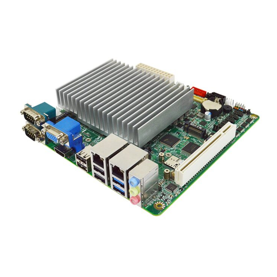
Chapter 1 Introduction of the Motherboard 1-1 Feature of Motherboard ◼ Onboard Intel® Processor N-series (TDP12W),with low power consumption never denies high performance ◼ Support 1* DDR5 4800MHz Single Channel SO-DIMM up to 32GB ◼ Integrated with 2* Realtek® RTL8111H 1GbE ◼... -
Page 7: Specification
1-2 Specification Spec Description ⚫ Design Mini-ITX SBC; PCB size: 17x 17 cm ⚫ Integrated with Intel® Alder Lake-N series CPU (TDP 12W) Embedded * Note: CPU model varies from different IPC options. Please consult your dealer for more information of onboard CPU.TDP varies depending on CPU. ⚫... - Page 8 ⚫ Optional for JMTX-ADN8-N97002 & JMTX-ADN8-N97008 ⚫ for detailed OS support information please visit our website OS Support for latest update *Note: The main differences among JMTX-ADN8 series are listed as below: Model TPM2.0 Onboard 64GB eMMC JMTX-ADN8-N97000 JMTX-ADN8-N97002 JMTX-ADN8-N97004...
-
Page 9: Layout Diagram
1-3 Layout Diagram Rear IO Diagram: 1 GbE COM1 RJ-45 LAN Ports VGA Port Serial Port (UL1 & UL2) USB 2.0 Port Line-in Port Line-out Port MIC Port COM2 HDMI Port USB 2.0 Port Serial Port USB 3.2 Gen.1 Port... - Page 10 M.2 E-key Slot Connector SIM Card (UL2) (M2E1) (SYSFAN1) Slot Line-in/Line-out/ Front Panel (SIMCARD1) Header (Audio1) (JW_FP1) GPIO Port Header Front Panel Audio (GPIO1) Serial Port Headers Header (F_Audio1) 3W Amplifier Header PCI Slot (COM3/4/5/6) (SPEAK1) Jetway Flash BIOS Header (REFLASH_CON1)
- Page 11 Jumper Positions: JPCOM1 JCLR1 JPLCD1 JPBKLT1 JPAT1 JP80P1 JPM2B1 JPCOM3 JPM2E1...
- Page 12 Jumpers Location Name Description Pitch JP80P1 Set GPIO 3-Pin Block 2.0mm JPCOM1 COM1 Header Pin-9 Function Select 4-Pin Block 2.0mm JPCOM3 COM2 Header Pin-9 Function Select 4-Pin Block 2.0mm JPLCD1 LVDS Panel VCC Power Select 4-Pin Block 2.0mm JPBKLT1 LCD BACKLIGHT VCC Power Select 3-Pin Block 2.0mm JPM2B1...
- Page 13 Headers & Wafers Location Name Description Pitch LVDS_EDP1 LVDS/eDP Port Header 30-pin Block 1.25mm REFLASH_CO Jetway Flash BIOS Header 20-pin Block 2.0mm GPIO1 GPIO Port Header 10-pin Block 2.0mm COM3~COM6 Serial Port Header 9-pin Block 2.0mm FP_USB1 USB 2.0 Header 9-pin Block 2.0mm...
-
Page 14: Chapter 2 Hardware Installation
Chapter 2 Hardware Installation 2-1 Jumper Settings JPLCD1 (4-pin): LVDS Panel VCC Power Select (2.0mm pitch) *Note: Maximum current limit is while using 3.3V, 5V or 12V. JPBKLT1 (3-pin): LCD BACKLIGHT VCC Power Select (2.0mm pitch) 2-3 Closed: 1-2 Closed: Backlight = +12V Backlight = +5V *Note: Maximum current limit is... - Page 15 JPCOM1 (4-pin): COM Header Pin9 Select (2.0mm pitch) *Note: Maximum current limit is 500mA while using 5V or 12V. JPCOM3 (4-pin): COM Header Pin9 Select (2.0mm pitch) 2-4 Closed: 3-4 Closed: 4-6 Closed: RI=RING; RI=+5V; RI=+12V. *Note: Maximum current limit is 500mA while using 5V or 12V.
- Page 16 JP80P1 (3-pin): Set GPIO (2.0mm pitch) JPAT1 ( 3-pin): ATX Mode / AT Mode Select (2.0mm pitch) 2-3 Closed: 1-2 Closed: AT Mode ATX Mode *ATX Mode Selected: Press power button to power on after power input ready; AT Mode Selected: Directly power on as power input ready.
- Page 17 JPM2B1 (3-pin): Power Select (2.0mm pitch) JPM2E1 (3-pin): Power Selet (2.0mm pitch)
-
Page 18: Connectors , Headers & Wafers
JCLR1 (8-pin): Clear RTC/ Clear CMOS/ ME Disable (2.0mm pitch) Connectors, Headers and Wafers 2-2-1 Rear I/O Panel Connectors Icon Name Function This audio jack can function as audio Line-in, Line-out & MIC-in combo connector with compatible cable Audio Line-In/ Line-Out connection. - Page 19 RJ-45 LAN Port: This connector is standard RJ-45 LAN jack for Network connection which supports10/100/1000 Mbps Ethernet data transfer Top: 1Gbps rate RJ-45 LAN Port Type-A USB3.2 Gen.1 Port: to connect USB keyboard, mouse or other devices compatible with Bottom: Type-A USB3.2 USB3.2 Gen.
- Page 20 RJ-45 Ethernet Connectors ** There are two LED next to the RJ-45 LAN port. Please refer to the table below for LAN port LED indications. For UL1/UL2 (RTL8111H GbE) 1.0Gbps RJ-45 LAN port LED Signals: (2) COM1_2 (9-pin Block): COM1 & COM2 Serial Port COM1/COM2: RS232/422/485...
-
Page 21: Motherboard Internal Connectors
2-2-2 Motherboard Internal Connector (1) ATXPWR(24-pin block): Main Power Connector (2) SATA1 (7-pin): SATAIII Port connector This is a high-speed SATAIII port that supports 6GB/s transfer rate. Pin No. Definition SATA1... -
Page 22: Pin Definition For Headers & Wafers
(3) CPUFAN1/SYSFAN1 (4-pin): CPU FAN and System FAN Connector CPUFAN1 Pin1 SYSFAN1 +12V Fan Power Fan Speed Control *Note: Maximum current limit is 1.5A while using 12V working voltage. 2-2-3 Pin Definition for Headers & Wafers SPEAK1 (4-pin): 3W Amplifier Wafer (2.0mm pitch) SPEAK1... - Page 23 GPIO1 (10-pin): GPIO Header (2.0mm pitch) GPIO1 *Note: 1.Maximum current limit is while using 5V working voltage; 2. Please refer to Page-12 JP80P1 jumper settings for GPIO1 80Port or GPIO Port function select. FP_USB1 (9-pin): USB2.0 Header (2.0mm pitch) FP_USB1 *Note: Maximum current limit is 500mA x 2...
- Page 24 FP_USB2 (5-pin): USB2.0 Header (2.0mm pitch) FP_USB2 *Note: Maximum current limit is 500mA x 1 in total while using 5V working voltag...
- Page 25 LVDS_EDP1 (30-pin): 24-bit Dual Channel LVDS or 2-Lane eDP Header (1.25mm pitch) LVDS_EDP Pin Define Pin No. Pin No. Pin Define LVDSB_DATAN3 Pin 1 Pin 2 LVDSB_DATAP3 LVDS_CLKBN Pin 3 Pin 4 LVDS_CLKBP LVDSB_DATAN2 Pin 5 Pin 6 LVDSB_DATAP2 LVDSB_DATAN1 Pin 7 Pin 8 LVDSB_DATAP1...
- Page 26 INVERTER1 (8-pin): LVDS Inverter Connector (2.0mm pitch) INVERTER1 Warning! Find Pin-1 location of the inverter and make sure that the installation direction is correct! Otherwise serious harm will occur to the board/display panel!! *Note: Maximum current limit is while using 5V or 12V. COM3/4/5/6 (9-pin): RS232 Serial Port Headers (2.0mm pitch) Pin1...
- Page 27 SMBUS1 (5-Pin): SMBUS Header (2.0mm pitch) SMBUS1 Pin 1 SMBUS_CLK VCC3 SMBUS_DATA SMBUS_ALERT VCC3 VCC3 VCC3 *Note: Maximum current limit is 500mA while using 3V working voltage. I2C1 (5-pin): I2C Header (2.0mm pitch) I2C1 Pin 1 VCC3 I2C_SDA I2C_SCL VCC3 VCC3 *Note: Maximum current limit is 500mA...
- Page 28 JW_FP1 (9-pin): Front Panel Header (2.54mm pitch) JW_FP1 *Note: Maximum current limit is while using 5V working voltage. F_Audio1 (9-pin): Front Panel Audio Header (2.00mm pitch) F_AUDIO1...
-
Page 29: Maximum Voltage & Current Limit
REFLASH_CON1 (20-pin): BIOS Update (2.00mm pitch) RELASH_CON1 2-3 Maximum Voltage & Current Limit Below is a list of maximum voltage & Current Limit specification for motherboard interface (including but not limited to slots, connectors and headers) for setup reference: Parts Working Voltage Current Support Ul1= 500mA x2... -
Page 30: Chapter 3 Introducing Bios
Chapter 3 Introducing BIOS Notice! The BIOS options in this manual are for reference only. Different configurations may lead to difference in BIOS screen and BIOS screens in manuals are usually the first BIOS version when the board is released and may be different from your purchased motherboard. Users are welcome to download the latest BIOS version form our official website. -
Page 31: Bios Menu Screen
BIOS Boot Menu Screen (boot device options please refer to actual configuration) BIOS Menu Screen The following diagram show a general BIOS menu screen: Menu Bar General Help Items Current Setting Value Function Keys Menu Items... -
Page 32: Function Keys
Function Keys In the above BIOS Setup main menu of, you can see several options. We will explain these options step by step in the following pages of this chapter, but let us first see a short description of the function keys you may use here: ⚫... -
Page 33: Memu Bars
3-5 Menu Bars There are six menu bars on top of BIOS screen: Main To change system basic configuration Advanced To change system advanced configuration Chipset To change chipset configuration Security Password settings Boot To change boot settings Save & Exit Save setting, loading and exit options. -
Page 34: Advanced Menu
System Date Set the date. Please use [Tab] to switch between date elements. System Time Set the time. Please use [Tab] to switch between time elements. 3-7 Advanced Menu Connectivity Configuration Use this item to configure Connectivity related options. Press [Enter] to make settings for the following sub-items: CNVi CRF Present CNVi Mode... - Page 35 The optional settings: [Disabled Integrated]; [Auto Detection]. [Auto Detection] means that if Discrete solution is discovered it will be enabled by default. Otherwise Integrated solution (CNVi) will be enabled; [Disabled Integrated] disables Integrated Solution. CPU Configuration Press [Enter] to view current CPU configuration and make settings for the following sub-items: ...
- Page 36 ‘ ’ ; *Note: Turbo Mode is only for JMTX-ADN8 single board model Disabled only for Barebone model used) C states Use this item to enable or disable CPU Power Management. When set as [Enabled], it allows CPU to go to C states when it’s not 100% utilized. C states Set the default value to: [Enabled] The optional settings: [Disabled];...
- Page 37 Power Limit 1 Use this item to set Power Limit 1 in Milli Watts. BIOS will round to the nearest 1/8W when programming. 0 = no custom override. For 12.50W, enter 12500. Overclocking SKU: Value must be between Max and Min Power Limits (specified by PACKAGE_POWER_SKU_MSR).
- Page 38 GT-Power Management Control Press [Enter] to make settings for the following sub-items: RC6(Render Standby) Use this item to check to enable render standby support. RC6(Render Standby) Set the default value to: [Enabled] The optional settings: [Disabled]; [Enabled]. Maximum GT frequency Use this item to Maximum GT frequency limited by the user.
- Page 39 The optional settings: [Disabled]; [Enabled]. SHA256 PCR Bank Set the default value to: [Enabled] SHA384 PCR Bank Use this item to enable or disable SHA384 PCR Bank. The optional settings: [Disabled]; [Enabled]. SHA384 PCR Bank Set the default value to: [Disabled] Pending Operation Use this item to schedule an operation for security device.
- Page 40 Change Settings Use this item to select an optimal settings for super IO device. The optional settings are: [Auto]; [IO=3F8h; IRQ=4]; [IO=2F8h; IRQ=3]; [IO=3E8h; IRQ=4]; [IO=2E8h; IRQ=3]. Change Settings Set the default value to: [Auto] Transmission Mode Select The optional settings are: [RS422]; [RS232]; [[RS485]. Transmission Mode Select Set the default value to: [RS232] Mode Speed Select Use this item to RS232/RS422/RS485 Speed Select.
- Page 41 The optional settings are: [RS232/RS422/RS485=250Kbps]; [RS232=1Mbps, RS422/RS485=10Mbps]. Mode Speed Select default value [RS232=1Mbps, RS422/RS485=10Mbps] Serial Port 3 Configuration Press [Enter] to make settings for the following items: Serial Port Use this item to enable or disable serial port (COM). The optional settings: [Disabled];...
- Page 42 Use this item to enable or disable serial port (COM). The optional settings: [Disabled]; [Enabled]. Serial Port Select Set the default value to: [Enabled] When set as [Enabled], user can make settings in the following items that appear: Change Settings Use this item to select an optimal setting for super IO device.
- Page 43 JCLR1 jumper setting for Case Open Detection); if Pin 7&8 of JCLR1 are short, system will show Case Open Message during POST. WatchDog Reset Timer Use this item to support WDT reset function. The optional settings: [Disabled]; [Enabled]. WatchDog Reset Timer Set the default value to: [Disabled] When set as [Enabled], user can make settings in the following items that appear: WatchDog Reset Timer Value User can set a value in the range of [10] to [255] seconds or [1] to [255] minutes.
- Page 44 COM1 Console Redirection Console Redirection enable or disable. The optional settings: [Disabled]; [Enabled]. Console Redirection Set the default value to: [Disabled] When set as [Enabled], user can make further settings in the ‘Console Redirection Settings’ screen: Console Redirection Settings The settings specify how the host computer and the remote computer (which the user is using) will exchange data.
- Page 45 [Odd]: parity bit is 0 if num of 1’s in the data bits is odd; [Mark]: parity bit is always 1; [Space]: parity bit is always 0; Parity Set the default value to: [None] [Mark] and [Space]: parity do not allow for error detection. They can be used as an additional data bit.
- Page 46 Putty KeyPad Use this item to select FunctionKey and KeyPad on Putty. The optional settings: [VT100]; [LINUX]; [XTERMR6]; [SCO]; [ESCN]; [VT400]. Putty KeyPad Set the default value to: [VT100] Serial Port for Out-of-Band Management/ Windows Emergency Management Services (EMS) Console Redirection EMS Use this item to enable or disable console redirection.
- Page 47 the buffers are empty, a “start” signal can be sent to re-start the flow. Hardware flow control uses two wires to send start/stop signals. The optional settings: [None]; [Hardware RTS/CTS]; [Software Xon/Xoff]. Flow Control EMS Set the default value to: [None] Data Bits EMS The default setting is: [8].
- Page 48 CPUFAN Idle-Speed Temperature Use this item to set CPUFAN idle speed temperature. Fan will run at idle speed when below this pre-set temperature. CPUFAN Idle-Speed Temperature Set the default value to: [40] CPUFAN Idle-Speed Duty Use this item to set CPUFAN idle speed duty. Fan will run at idle speed when below this pre-set duty.
- Page 49 XHCI Hand-off This is a workaround for OSes without XHCI hand-off support. The XHCI ownership change should be claimed by XHCI driver. The optional settings: [Enabled]; [Disabled]. XHCI Hand-off Set the default value to: [Enabled] USB Mass Storage Driver Support Use this item to enable or disable USB Mass storage driver support.
- Page 50 The optional settings: [Disabled]; [Enabled]. Network Stack Set the default value to: [Disabled] When set as [Enabled], the following sub-items shall appear: IPv4 PXE Support Use this item to enable/disable IPv4 PXE Boot Support. When set as [Disabled], IPv4 PXE boot support will not be available. The optional settings: [Disabled];...
- Page 51 The optional settings: [Disabled]; [Enabled]. Wake-up System With Fixed Time Set the default value to: [Disabled] When set as [Enabled], user can make settings in the following items that appear: Wake-up Hour Use this item to select 0-23 for example enter 3 for 3am and 15 for 3pm. Wake-up Hour Set the default value to: [0] Wake-up Minute Use this item to select 0-59.
-
Page 52: Chipset Menu
PTT Capability/state TPM Device Selection TPM Device Selection Set the default value to: [dTPM] 3-8 Chipset Menu System Agent (SA) Configuration Press [Enter] to make settings for the following sub-items: System Agent (SA) Configuration GTT Size Use this item to select GTT Size. The optional settings are: [2MB];... - Page 53 DVMT Pre-Allocated Select DVMT 5.0 Pre-Allocated (Fixed) Graphics Memory size used by the Internal Graphics Device. The optional settings: [32M]; [64M]; [96M]; [128M]; [160M]; [8M]; [12M]; [16M]; [20M]; [24M]; [28M]; [32M/F7]; [36M]; [40M]; [44M]; [48M]; [52M]; [56M]; [60M]. DVMT Pre-Allocated Set the default value to: [128M] Active LFP Use this item to select the Active LFP Configuration.
- Page 54 PCH-IO Configuration SATA Configuration SATA Device Options Settings. SATA Configuration SATA Controller(s) Use this item to enable/disable SATA Device. The optional settings are: [Enabled]; [Disabled]. SATA Controller(s) Set the default value to: [Enabled] When set as [Enabled], the following sub-items shall appear: SATA Mode Selection Use this item to determines how SATA controller(s) operate.
- Page 55 *Note: "eMMC mode" is only applicable to specific models (64GB For JMTX-ADN8-N97004/JMTX-ADN8-N97008) The optional settings: [Disabled]; [Enabled]. I2C0 Controller Use this item to enables/disables SerialIo Controller If given device is function 0 PSF disabling is skipped. PSF default will remain and device PCI CFG Space will still be visible.
-
Page 56: Security Menu
3-9 Security Menu Security menu allow users to change administrator password and user password settings. Administrator Password If there is no password present on system, please press [Enter] to create new administrator password. If password is present on system, please press [Enter] to verify old password then to clear/change password. - Page 57 Secure Boot Press [Enter] to make customized secure settings: System Mode Secure Boot Secure Boot feature is Active if Secure Boot is Enabled, Platform Key(PK) is enrolled and the System is in User mode. The mode change requires platform reset.
- Page 58 The optional settings: [Disabled]; [Enabled]. Factory Key Provision Set the default value to: [Disabled] Restore Factory Keys Use this item to force system into User Mode. Install factory default Secure Boot key databases. Reset To Setup Mode Use this item to Delete all Secure Boot key databases from NVRAM. ...
-
Page 59: Boot Menu
3-10 Boot Menu Boot Configuration Setup Prompt Timeout Use this item to set number of seconds to wait for setup activation key. 65535 (0xFFFF) means indefinite waiting. Setup Prompt Timeout Set the default value to: [1] Bootup NumLock State Use this item to select keyboard NumLock state. The optional settings: [On];... -
Page 60: Save & Exit Menu
Quiet Boot Set the default value to: [Disabled] Boot Option Priorities 3-11 Save & Exit Menu Save Changes and Reset This item allows user to reset the system after saving the changes. Discard Changes and Reset This item allows user to reset the system setup without saving any changes. Restore Defaults Use this item to restore /load default values for all the setup options. - Page 61 Restore User Defaults Use this item to restore the user defaults to all the setup options. Boot Override...
Need help?
Do you have a question about the JMTX-ADN8 Series and is the answer not in the manual?
Questions and answers