Table of Contents
Advertisement
Quick Links
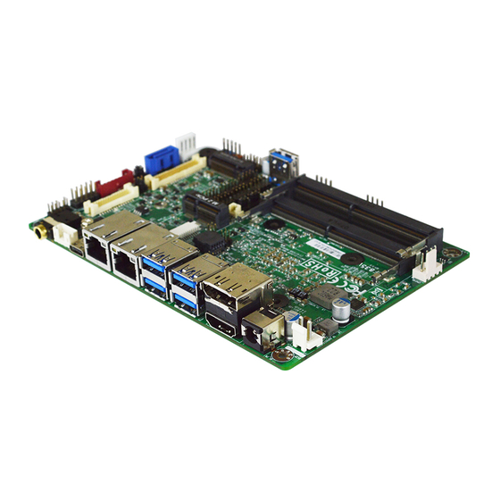
NF835V Series
User's Manual
NO.: G03-NF835V-F
Revision: 1.0
Release date: July 6, 2022
Trademark:
* Specifications and Information contained in this documentation are furnished for information use only, and are
subject to change at any time without notice, and should not be construed as a commitment by manufacturer.
Advertisement
Table of Contents

Related Manuals for JETWAY NF835V Series


Summary of Contents for JETWAY NF835V Series
- Page 1 NF835V Series User’s Manual NO.: G03-NF835V-F Revision: 1.0 Release date: July 6, 2022 Trademark: * Specifications and Information contained in this documentation are furnished for information use only, and are subject to change at any time without notice, and should not be construed as a commitment by manufacturer.
- Page 2 Environmental Protection Announcement Do not dispose this electronic device into the trash while discarding. To minimize pollution and ensure environment protection of mother earth, please recycle.
-
Page 3: Table Of Contents
TABLE OF CONTENT ENVIRONMENTAL SAFETY INSTRUCTION................... iv USER’S NOTICE............................ v MANUAL REVISION INFORMATION....................v ITEM CHECKLIST..........................v CHAPTER 1 INTRODUCTION OF THE MOTHERBOARD FEATURE OF MOTHERBOARD..................1 SPECIFICATION........................2 LAYOUT DIAGRAM.......................3 CHAPTER 2 HARDWARE INSTALLATION JUMPER SETTING........................ 8 CONNECTORS AND HEADERS..................12 2-2-1 CONNECTORS......................12 2-2-2... -
Page 4: Environmental Safety Instruction
Environmental Safety Instruction Avoid the dusty, humidity and temperature extremes. Do not place the product in any area where it may become wet. 0 to 60 centigrade is the suitable temperature. (The figure comes from the request of the main chipset) ... -
Page 5: User's Notice
USER’S NOTICE COPYRIGHT OF THIS MANUAL BELONGS TO THE MANUFACTURER. NO PART OF THIS MANUAL, INCLUDING THE PRODUCTS AND SOFTWARE DESCRIBED IN IT MAY BE REPRODUCED, TRANSMITTED OR TRANSLATED INTO ANY LANGUAGE IN ANY FORM OR BY ANY MEANS WITHOUT WRITTEN PERMISSION OF THE MANUFACTURER. -
Page 6: Chapter 1 Introduction Of The Motherboard
Chapter 1 Introduction of the Motherboard 1-1 Feature of Motherboard Onboard Intel Whiskey Lake-U series processor, TDP 15W, never denies high ® performance Support 2* DDR4 2400MHz SO-DIMM, maximum capacity up to 64GB Integrated with 1* Intel ®... -
Page 7: Specification
1-2 Specification Spec Description Design 3.5”SBC; 8-Layers; PCB size: 14.8x 10.2 cm Integrated with Intel Whiskey Lake-U series CPU (TDP 15W) ® Embedded * Note: CPU model varies from different IPC options. Please consult your dealer for more information of onboard CPU. 2*DDR4 SO-DIMM slot support 2* DDR4 2400MHz non-ECC ... -
Page 8: Layout Diagram
1* 2-pin internal 9~24V DC-in power connector 1* Internal vertical USB 3.1 (Gen.2) port connector 1* SATA Power-out connector 1* CPU FAN header 1* Front panel header 1* 9-pin USB 2.0 header (Expansible to 2* USB 2.0 ports) ... - Page 9 Diagram-Front Side: Front Panel GPIO Port SATA Power-out SATAIII Port Audio Header Header Connector INVERTER Line-out Port Front Panel Header (JW_FP1) LVDS Header EDP Header Speaker Header M.2 M-key Slot USB 3.1 (Gen.2) USB 2.0 Header (M2M) Type-C Port Serial Port Headers (COM1~6) M.2 E-key Slot Vertical...
- Page 10 Jumper Positions: JBAT AT_COPEN...
- Page 11 Jumpers Jumper Name Description 4-Pin Block COM1 Header Pin-9 Function Select 4-Pin Block COM2 Header Pin-9 Function Select LCD_ BACKLIGHT VCC Select 4-Pin Block LCD Panel VCC Select 4-Pin Block JBAT Pin (1-2): Clear CMOS 4-Pin Block Pin (3-4): Flash Override AT_COPEN Pin (1-2): AT Mode Select 4-Pin Block Pin (3-4): Case Open Display Select...
- Page 12 Headers Header Name Description JW_FP Front Panel Header(PWR LED/ 9-pin Block HDD LED/Power Button /Reset) FP_USB22 USB 2.0 Header 9-pin Block FP_USB21 USB 2.0 Header 4-pin Block FP_AUDIO Front Panel Audio Header 9-pin Block SPK_CON 3W Amplifier Header 4-pin Block GPIO GPIO Port Header 10-pin Block...
-
Page 13: Chapter 2 Hardware Installation
Chapter 2 Hardware Installation 2-1 Jumper Settings JP1 (4-pin): COM1 Header Pin-9 Function Select (pitch 2.0mm) COM1 Header → COM1 1 3 5 1 3 5 3-4 Closed: 4-6 Closed: 2-4 Closed: RI= +5V; RI= +12V. RI=RS232; JP2 (4-pin): COM2 Header Pin-9 Function Select (pitch 2.0mm) COM2 Header →... - Page 14 JP3 (4-pin): LVDS/EDP LCD_BACKLIGHT Voltage Select (pitch 2.0mm) JP4 (4-pin): LVDS/EDP LCD Panel VCC Select (pitch 2.0mm)
- Page 15 Pin (1-2) of JBAT (4-pin): Clear CMOS Settings (pitch 2.0mm) Pin 1&2 of JBAT → Clear CMOS Pin1 1-2 Open: Normal(Default); JBAT Pin1 1-2 Closed: Clear CMOS(One Touch). Pin (3-4) of JBAT (4-pin): ME Flash Override Select (pitch 2.0mm) Pin 3&4 of JBAT →...
- Page 16 Pin (1-2) of AT_COPEN (4-pin): ATX Mode/AT Mode Select (pitch 2.0mm) Pin 1&2 of AT_COPEN → ATX/AT Mode Select Pin1 1-2 Open: ATX Mode Selected(Default); AT_COPEN Pin1 1-2 Closed: AT Mode Selected. *ATX Mode Selected: Press power button to power on after power input ready; AT Mode Selected: Directly power on as power input ready.
-
Page 17: Connectors And Headers
Detect’ function. In this case if your case is removed, next time when you restart your computer, a message will be displayed on screen to inform you of this. Connectors and Headers 2-2-1 Connectors (1) Rear I/O Connectors * Refer to Page-3 Rear IO Diagram. Icon Name Function... - Page 18 (2) DC2P(2-pin) : Internal 9~24V DC-in Power Connector Pin1 Pin No. Definition +9V~24VC DC-In DC2P Warning: Find Pin-1 position before connecting power cable to this 2-pin power connector. WRONG INSTALLATION DIRECTION WILL DAMAGE THE BOARD!! (3) SATA(7-pin): SATAIII Port connector This is a high-speed SATAIII port that supports 6GB/s transfer rate.
- Page 19 (4) SATAPWR (4-pin): SATA HDD Power-Out Connector SATAPWR Pin1 Warning: Make sure that Pin-1 of compatible SATA Power out connector is inserted into corresponding Pin-1 of SATAPWR connector to avoid possible damage to the board and hard disk driver! (5) CPUFAN (4-pin): CPU FAN Connector CPUFAN Pin1...
- Page 20 M2M: M.2 M-key Slot M2M M.2 M-Key slot supports compatible type 2242/2280 PCIe x4(NVMe) and SATA module. M2M Slot: M.2 Module Installation Guide Nut Location Card Length 4.2 cm 8 cm Module Type Type- 2242 Type- 2280 a) Remove the screw post and nut fixed b) Lock the screw post into the location at location MH4 by default (Skip corresponding to the length of the...
-
Page 21: Headers
c) Align and insert corresponding M.2 d) Tighten up the screw to secure the module, as the photo shows. module into the M.2 connector. Make sure not overtighten the screw to avoid possible damage to the module. 2-2-2 Headers JW_FP (9-pin): Front Panel Header (pitch 2.54mm) JW_FP RSTSW... - Page 22 FP_USB22 (9-pin): USB 2.0 Port Header (pitch 2.0mm) FP_USB22 +DATA +DATA -DATA -DATA Pin 1 FP_USB21 (4-pin): USB2.0 Header (pitch 2.54mm) +DATA -DATA FP_USB21 Pin 1...
- Page 23 FP_AUDIO (9-pin): Line-Out, MIC-In Header (pitch 2.0mm) This header connects to Front Panel Line-out, MIC-In connector with cable. FP_AUDIO SPK_CON (4-pin): 3W Amplifier Header SPK_CON...
- Page 24 GPIO (10-pin): GPIO Header (pitch 2.54mm) GPIO Pin1...
- Page 25 COM1/2/3/4/5/6(9-pin): Serial Port Headers (pitch 2.0mm) COM1: RS232/422/485 Serial Port Header. COM2/3/4/5/6: RS232 Serial Port Header. Pin NO. RS232 *RS422 *RS485 (optional) (optional) DATA- Pin 1 COM4 Pin 2 DATA+ COM2 Pin 3 Pin 4 COM6 Pin 5 *COM1 Pin 6 Pin 7 Pin 8 COM5...
- Page 26 EDP (40-pin): 4-lane eDP Header Pin 40 Pin 20 Pin21 Pin 1 Pin Define Pin NO. Pin NO. Pin Define Pin 40 Pin 20 LCD_VCC BL_PWR Pin 39 Pin 19 LCD_VCC BL_PWR Pin 38 Pin 18 LCD_VCC BL_PWR Pin 37 Pin 17 BL_PWR Pin 36...
- Page 27 LVDS (30-pin): 24-bit Dual Channel LVDS Header Pin 1 Pin 2 LVDS Pin 30 Pin29 Pin Define Pin NO. Pin NO. Pin Define LVDSB_DATAN3 Pin 1 Pin 2 LVDSB_DATAP3 LVDS_CLKBN Pin 3 Pin 4 LVDS_CLKBP LVDSB_DATAN2 Pin 5 Pin 6 LVDSB_DATAP2 LVDSB_DATAN1 Pin 7...
- Page 28 INVERTER (8-pin): LVDS Inverter Connector Pin No. Definition Backlight Enable INVERTER Backlight PWM PVCC PVCC Backlight Up SW Backlight Down SW Warning! Find Pin-1 location of the inverter and make sure that the installation direction is correct! Otherwise serious harm will occur to the board/display panel!! I2C_CON (4-pin): I2C Header (pitch 2.54mm) I2C_SDA...
- Page 29 PS2KBMS (6-pin): PS/2 Keyboard & Mouse Header (pitch 2.0mm) MS_DATA MS_CLK KB_CLK PS2KBMS KB_DATA Pin1 LAN_LED (4-pin): LAN Activity LED Header (pitch 2.0mm) LAN_LED Pin1 LAN1LED+ LAN1LED- LAN2LED- LAN2LED+...
- Page 30 WLAN_LED (4-pin): Wi-Fi & Bluetooth Activity LED Header (pitch 2.0mm) WLAN_LED Pin1 WIFI_LED+ WIFI_LED- BT_LED- BT_LED+...
-
Page 31: Chapter 3 Introducing Bios
Chapter 3 Introducing BIOS Notice! The BIOS options in this manual are for reference only. Different configurations may lead to difference in BIOS screen and BIOS screens in manuals are usually the first BIOS version when the board is released and may be different from your purchased motherboard. Users are welcome to download the latest BIOS version form our official website. -
Page 32: Bios Menu Screen
3-2 BIOS Menu Screen The following diagram show a general BIOS menu screen: Menu Bar General Help Items Current Setting Value Menu Items Function Keys BIOS Setup Menu Screen... -
Page 33: Function Keys
3-3 Function Keys In the above BIOS Setup main menu of, you can see several options. We will explain these options step by step in the following pages of this chapter, but let us first see a short description of the function keys you may use here: ... -
Page 34: Getting Help
3-4 Getting Help Main Menu The on-line description of the highlighted setup function is displayed at the top right corner the screen. Status Page Setup Menu/Option Page Setup Menu Press [F1] to pop up a small help window that describes the appropriate keys to use and the possible selections for the highlighted item. -
Page 35: Main Menu
3-6 Main Menu Main menu screen includes some basic system information. Highlight the item and then use the <+> or <-> and numerical keyboard keys to select the value you want in each item. System Date Set the date. Please use [Tab] to switch between date elements. System Time Set the time. -
Page 36: Advanced Menu
3-7 Advanced Menu Connectivity Configuration Press [Enter] to view current Connectivity related options: CNVi Configuration CNVi Mode This option configures connectivity options. The optional settings are: [Disable Integrated]; [Auto Detection]. [Auto Detection] means that if Discrete solution is discovered it will be enabled by default. - Page 37 The optional settings: [Disabled]; [Enabled]. When set as [Disabled] only one thread per enabled core is enabled. [Enabled]: for Windows and Linux (OS optimized for Hyper-Threading Technology). [Disabled]: for other OS (OS optimized not for Hyper-Threading Technology). *Note: ‘Hyper-Threading’ item may or may not show up, depending on different CPU.
- Page 38 The default setting is: [AHCI]. The optional settings are: [AHCI]; [RAID]. SATA Port The optional settings: [Disabled]; [Enabled]. Use this item to enable or disable each SATA port. Hot Plug Use this item to Designates this port as Hot pluggable. The optional settings: [Disabled];...
- Page 39 FW Image Re-Flash’ as [Enabled], save the settings and exit. The system will turn off and reboot after 4 seconds. If the user goes to BIOS screen again will find this item is set again as [Disabled], but user can still re-flash to update firmware next time.
- Page 40 Wake-up System With Fixed Time Use this item to enable or disable System wake on alarm event. The optional settings: [Disabled]; [Enabled]. When set as [Enabled], the following items shall appear: Wake-up Hour Use this item to select 0-23. For example enter 3 for 3am and 15 for 3pm. Wake-up Minute Use this item to select 0-59.
- Page 41 This function is supported when ‘ERP Support’ is set as [Disabled]. *Note: Internal USB Port S5 Power Use this item to enable or disable USB power after power shutdown. *Note: This function is supported when ‘ERP Support’ is set as [Disabled]. ...
- Page 42 Serial Port 2 Configuration Serial Port Use this item to enable or disable serial port (COM). The optional settings: [Disabled]; [Enabled]. When set as [Enabled], user can make further settings in the following items: Change Settings Use this item to select an optimal setting for Super IO Device. The optional settings: [IO=2F8h;...
- Page 43 Change Settings Use this item to select an optimal setting for Super IO Device. The optional settings: [IO=2E8h; IRQ=10;]; [IO=3F8h; IRQ=3,4,5,7,10,11;]; [IO=2F8h; IRQ=3,4,5,7,10,11;]; [IO=3E8h; IRQ=3,4,5,7,10,11;]; [IO=2E8h; IRQ=3,4,5,7,10,11;]; [IO=3E0h; IRQ=3,4,5,7,10,11;]; [IO=2E0h; IRQ=3,4,5,7,10,11;]. ► Serial Port 5 Configuration Press [Enter] to make settings for the following sub-items: Serial Port 5 Configuration Serial Port Use this item to enable or disable serial port (COM).
- Page 44 IRQ=3,4,5,7,10,11;]; [IO=3E0h; IRQ=3,4,5,7,10,11;]; [IO=2E0h; IRQ=3,4,5,7,10,11;]. WatchDog Reset Timer Use this item to enable or disable WDT reset function. When set as [Enabled], the following sub-items shall appear: WatchDog Reset Timer Value User can select a value in the range of [4] to [255] seconds when ‘WatchDog Reset Timer Unit’...
- Page 45 make further settings in ‘SmartFAN Configuration’. PC Health Status SmartFAN Configuration Press [Enter] to make settings for ‘SmartFAN Configuration’: SmartFAN Configuration CPUFAN Smart Mode The optional settings: [Disabled]; [Enabled]. When set as [Enabled], the following sub-items shall appear: CPUFAN Full-Speed Temperature Use this item to set CPUFAN full speed temperature.
- Page 46 Console Redirection Settings The settings specify how the host computer and the remote computer (which the user is using) will exchange data. Both computers should have the same or compatible settings. Press [Enter] to make settings for the following items: Terminal Type The optional settings: [VT100];...
- Page 47 receiving buffers are full, a “stop” signal can be sent to stop the data flow. Once the buffers are empty, a “start” signal can be sent to re-start the flow. Hardware flow control uses two wires to send start/stop signals. The optional settings: [None];...
- Page 48 When [Bootloader] is selected, then Legacy Console Redirection is disabled before booting to legacy OS. When [Always Enabled] is selected, then Legacy Console Redirection is enabled for legacy OS. Default setting for this option is set to [Always Enabled]. Serial Port for Out-of-Band Management/ Windows Emergency Management Services (EMS) Console Redirection The optional settings: [Disabled];...
- Page 49 Flow Control Flow control can prevent data loss from buffer overflow. When sending data, if the receiving buffers are full, a “stop” signal can be sent to stop the data flow. Once the buffers are empty, a “start” signal can be sent to re-start the flow. Hardware flow control uses two wires to send start/stop signals.
- Page 50 USB transfer time-out Use this item to set the time-out value for Control, Bulk, and Interrupt transfers. The optional settings: [1 sec]; [5 sec]; [10 sec]; [20 sec]. Device reset time-out Use this item to set USB mass storage device Start Unit command time-out. The optional settings: [10 sec];...
- Page 51 Use this item to set wait time to press [ESC] key to abort the PXE boot. Use either +/- or numeric keys to set the value. Media Detect Count Use this item to set number of times presence of media will be checked. Use either +/- or numeric keys to set the value.
-
Page 52: Chipset Menu
3-8 Chipset Menu System Agent (SA) Configuration Press [Enter] to make settings for the following sub-items: System Agent (SA) Configuration VT-d VT-d The optional settings: [Disabled]; [Enabled]. ► Memory Configuration Press [Enter] to view brief information for the working memory module. ►... - Page 53 has no effect if external graphics present. Secondary boot display selection will appear based on your selection VGA modes will be supported only on primary display. The optional settings: [VBIOS Default]; [HDMI]; [DP]; [eDP/LVDS]. *Note: In the case that the ‘Primary IGFX Boot Display’ is select as [DP], [HDMI], or [eDP/LVDS], user can make further settings in ‘Secondary IGFX Boot Display’: Secondary IGFX Boot Display...
- Page 54 Panel Type Use this item to manually select LCD panel type. The optional setting: [800x 480 18bit Single]; [800x 600 18bit Single]; [800x 600 24bit Single]; [1024 x 600 18bit Single]; [1024 x 768 18bit Single]; [1024 x 768 24bit Single]; [1280 x 768 24bit Single]; [1280 x 800 18bit Single]; [1280 x 800 24bit Single];...
- Page 55 M2E Slot Use this item to enable or disable M2E slot PCI Express root port function. The optional settings: [Disabled]; [Enabled]. When set as [Enabled], user can make further settings in ‘Speed’: Speed The optional settings: [Auto]; [Gen1]; [Gen2]. M2M Slot Use this item to enable or disable M2M slot PCI Express root port function.
-
Page 56: Security Menu
3-9 Security Menu Security menu allow users to change administrator password and user password settings. Administrator Password If there is no password present on system, please press [Enter] to create new administrator password. If password is present on system, please press [Enter] to verify old password then to clear/change password. - Page 57 Secure Boot Press [Enter] to make customized secure settings: System Mode Secure Boot The optional settings: [Disabled]; [Enabled]. Secure Boot feature is active if Secure Boot is enabled, Platform Key(PK) is enrolled and the system is in User mode. The mode change requires platform reset.
- Page 58 Use this item to force system into User Mode. Install factory default Secure Boot Key databases. Reset to Setup Mode Use this item to Delete all secure boot key databases from NVRAM Export Secure Boot variables Use this item to copy NVRAM content of secure boot variables to files in a root folder on a file system device.
-
Page 59: Boot Menu
3-10 Boot Menu Boot Configuration Setup Prompt Timeout Use this item to set number of seconds to wait for setup activation key. 65535 (0XFFFF) means indefinite waiting. Bootup Numlock State Use this item to select keyboard numlock state. The optional settings: [On]; [Off]. Quiet Boot The optional settings: [Disabled];... -
Page 60: Save & Exit Menu
3-11 Save & Exit Menu Save Options Save Changes and Reset This item allows user to reset the system after saving the changes. Discard Changes and Reset This item allows user to reset the system without saving any changes. Default Options Restore Defaults Use this item to restore /load default values for all the setup options.
Need help?
Do you have a question about the NF835V Series and is the answer not in the manual?
Questions and answers