Table of Contents
Advertisement
Available languages
Available languages
Quick Links
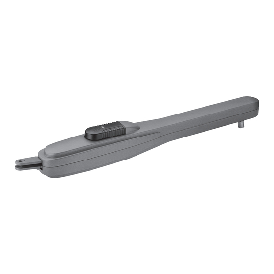
PRINCE 24V
Brevettato - Patented
N. 1 503 019 - US 7,000,353 B2
Scarica questo manuale sul tuo cellulare
Téléchargez ce manuel sur votre mobile
Download this manual on your mobile
Laden Sie dieses Handbuch auf Ihr Handy herunter
Descarga este manual en tu móvil
Operatore
Operateur
Operator
Torantrieb
Operador
PRINCE 24V
KIT PRINCE 24V
ITALIANO pag. 05 / FRANÇAIS pag. 18 / ENGLISH page 31 / DEUTSCH pag. 44 / ESPAÑOL pag. 57
con / avec / with / mit
Alimentazione
Alimentation
Power Supply
Stromspannung
Alimentacion
230V 50/60Hz
120V 60Hz
Il corretto funzionamento dell'operatore è garantito solo se viene gestito da un quadro di comando RIB
Le bon fonctionnement de l'opérateur n'est garanti que s'il est géré par un panneau de contrôle RIB
The correct operation of the operator is guaranteed only if it is managed by a RIB control panel
Die korrekte Bedienung des Bedieners ist nur gewährleistet, wenn er von einem RIB-Bedienpanel verwaltet wird
El funcionamiento correcto del operador solo está garantizado si está gestionado por un panel de control RIB
B2 24V-CRX
Peso max anta
Spinta max
Poids maxi battant
Poussée maxi
Max leaf weight
Max thrust
Max. Torgewicht
Max Schubkraft
Peso max hoja
Empuje max.
250 kg / 550 lbs
145 kg / 319 lbs
Disegni tecnici per progetti
Dessins techniques pour les projets
Technical drawings for projects
Technische Zeichnungen für Projekte
Dibujos técnicos para proyectos.
Manuali online interattivi
Manuels interactifs en ligne
Interactive online manuals
Interaktive Online-Handbücher
Manuales interactivos en línea.
Vedere pagina 17
Voir page 30
See page 43
Siehe Seite 56
Ver página 69
Codice
Code
Code
Code
Codigo
AA14031
a richiesta/on request
AD00738
a richiesta/on request
Advertisement
Table of Contents

Related Manuals for RIB AD00738


Summary of Contents for RIB AD00738
- Page 1 Le bon fonctionnement de l’opérateur n’est garanti que s’il est géré par un panneau de contrôle RIB The correct operation of the operator is guaranteed only if it is managed by a RIB control panel Die korrekte Bedienung des Bedieners ist nur gewährleistet, wenn er von einem RIB-Bedienpanel verwaltet wird El funcionamiento correcto del operador solo está...
- Page 2 2° - En ce qui concerne la section et le type des câbles, RIB conseille d’utiliser un câble de 2° - Per la sezione ed il tipo dei cavi la RIB consiglia di utilizzare un cavo di tipo H05RN-F con type H05RN-F ayant une section minumum de 1,5 mm 2 et de toute façon, s’en tenir à...
- Page 3 Kontaktöffnung von 3 mm), der ein von den internationalen Normen 2° - For the section and the type of the cables RIB advices to use a cable of H05RN-F type anerkanntes Konformitätszeichen besitzt. Solch ein Geraet muss vor Vandalismus with 1,5 sqmm minimum section and, however, to keep to the IEC 364 and installation geschuetzt werden (z.B.mit einen Schluesselkatsten in einem Panzergehaeuse).
- Page 4 L’eliminazione dei materiali va fatta rispettando le norme vigenti. Non gettate il vostro 2° - Para la sección y el tipo de los cables, RIB aconseja utilizar cables de tipo H05RN-F con apparecchio scartato, le pile o le batterie usate nei rifiuti domestici. Avete la responsabilità di sección mínima de 1,5 mm 2 e igualmente atenerse a la norma IEC 364 y a las normas de...
- Page 5 LAYOUT IMPIANTO CARATTERISTICHE TECNICHE PRINCE è un’operatore in grado di movimentare cancelli a battente con ante lunghe fino a 3 m e pesanti fino a 250 kg (Fig. 1). PRINCE è stato concepito per lavorare senza finecorsa elettrici, ma solo meccanici. NOTA BENE: Per mantenere una efficace posizione di chiusura é...
- Page 6 INSTALLAZIONE PRINCE CONTROLLO PRE-INSTALLAZIONE Le ante devono essere solidamente fissate ai cardini delle colonne, non devono flettere durante il movimento e devono muoversi senza attriti. Prima d’installare PRINCE è meglio verificare tutti gli ingombri necessari per poterlo installare. Se il cancello si presenta come da Fig. 1 non occorrono modifiche. È...
- Page 7 Rispettare la misura e assicurarsi che l’operatore sia orizzontale α Misure da rispettare per una corretta installazione 108° 105° 103° * Attacco anta 99° Qualora il pilastro fosse molto largo e non fosse possibile installare 1-3m 99° l’elettroriduttore rispettando la misura (B), è indispensabile creare una nicchia nel pilastro o spostare il cancello sullo spigolo.
-
Page 8: Manutenzione
FERMO MECCANICO - OPTIONAL (Cod. ACG8088) Fermo meccanico OPTIONAL per fermare la chiusura in caso il cancello sia privo di un fermo a terra. REGOLAZIONE FINECORSA MECCANICI Per posizionare i fermi si deve agire come da schema (Fig. 11). Per ottenere l’apertura desiderata è sufficiente spostare il fermo (A) e bloccarlo serrando la vite da 8mA con una chiave fissa n°13. - Page 9 COLLEGAMENTI ELETTRICI B2 24V cod. AC08070...
- Page 10 LOW SP Alimentazione 230 Vac 50/60 Hz - esterna alla scheda RADIO Connettore per modulo radio ACG8069 (120 V 60 Hz a richiesta) Connettore per radio ricevitore RIB ad innesto con RADIO A+TEST Positivo per alimentazione autotest fotocellule alimentazione a 24Vdc BATTERY CHARGER Connettore per scheda di ricarica batteria a 24Vdc (cod.
- Page 11 B - IMPOSTAZIONI TRIMMER SENS Di fabbrica abilitato e led DL14 acceso (trimmer a metà corsa) La centrale B2 24V è dotata di sensore di impatto che inverte la marcia del cancello in caso DIP 1 (ON) - CONTROLLO SENSO DI ROTAZIONE DEI MOTORI (PUNTO C) questo impatti contro cose o persone (in conformità...
- Page 12 5 - Raggiunto il fermo meccanico di apertura, il SENSORE DI IMPATTO ferma M2 (con attimo il pulsante PROG. Il led DL12 smette di lampeggiare. memorizzazione del tempo e dei livelli di corrente assorbiti lungo il percorso). 4 - Riposizionare DIP 1 su OFF e DIP 2 su OFF. 6 - Premete il pulsante PROG./RADIO/OPEN/START =>...
-
Page 13: Funzionamento Accessori Di Sicurezza
R-AUX funziona normalmente come luce di cortesia per 3 minuti. PULSANTE DI CHIUSURA (COM A+/CLOSE) Tramite App RIB GATE è possibile configurare il funzionamento di questo relé a piacere. A cancello fermo comanda il moto di chiusura. La programmazione può essere eseguita solo a cancello fermo. -
Page 14: Caratteristiche Tecniche
Collegare il trasmettitore della fotocellula a A+ TEST/A- e impostare DIP 7 su ON. N.B.: Max 3 W. Se si eccede con le spie, la logica del quadro ne risulterà compromessa con Il monitoraggio consiste in un Test Funzionale della fotocellula, eseguito prima di ogni manovra. possibile blocco delle operazioni. - Page 15 interrompendo l'uscita a loro assegnata. A fronte di una ricerca guasti si consiglia di scollegare tutti i connettori estraibili e di inserirli uno a volta in modo da identificare più facilmente la causa del guasto. TABELLA RIASSUNTIVA ALLARMI VISIVI E SONORI SEGNALAZIONI IN FASE DI PROGRAMMAZIONE EVENTO STATO BUZZER...
- Page 16 Costa con resistenza 8,2 KΩ. Togliere la resistenza o configurare l’ingresso EDGE tramite App Il buzzer emette 2 toni prolungati e il cancello non si muove RIB GATE Il telecomando non funziona. Led DL12 acceso rosso fisso Mancanza modulo radio nel connettore J6 o modulo radio guasto.
- Page 17 FIT SLIM EN12978 - EN13849-2 SAIL 102.5 47.5 SAIL arancio con scheda intermittente incorporata cod. ACG7072 FOTOCELLULE DA PARETE cod. ACG8032B SAIL bianco con scheda intermittente incorporata cod. ACG7078 COPPIA DI COLONNINE PER FIT SLIM cod. ACG8065 SUPPORTO LATERALE SAIL cod.
-
Page 18: Caracteristiques Techniques
SCHÉMA DÉTAILLÉ DE L’INSTALLATION CARACTERISTIQUES TECHNIQUES PRINCE est un opérateur utilisé pour manoeuvrer des portails à battans jusqu’à 3 m de longeur et 250 kg de poids (Fig.1). Les opérateurs PRINCE utilisent les fin de course mécaniques intégrés, de ce fait évitant le devoir installer des fins de course électriques. - Page 19 INSTALLATION PRINCE CONTROLE PRE-INSTALLATION Le portail à battant doit être solidement fixé aux poteaux, ne doit pas flechir pendant le mouvement et doit pouvoir manoeuvrer sans effort. Avant d’installer PRINCE, il convient de verifier tous les encombrements necessaires pour proceder à l’installation. Si le portail se presente comme indiqué...
- Page 20 Se conformer à la mesure et faire en sorte que l’opérateur est horizontale α Mesures à respecter pour une correcte installation 108° 105° * Attache vantail 103° 99° Si le pilier est très large et qu’il n’est pas possible d’installer le motoréducteur en respectant la mesure (B), il faut realiser une niche 1-3m 99°...
-
Page 21: Entretien
ARRÊT MÉCANIQUE - OPTION (Cod. ACG8088) Arrêt mécanique en OPTION pour arrêter la fermeture si le portail n’est pas pourvu de dispositif d’arrêt au sol. REGLAGE FINS DE COURSE MECANIQUES Pour positionner les colliers, il est necessaire agir selon les indications du schema (Fig. 11). Pour obtenir l’ouverture desirée, il suffit de déplacer le collier (A) et de le bloquer en vissant la vis M8 avec une clé... - Page 22 BRANCHEMENTS ÉLECTRIQUES B2 24V cod. AC08070...
- Page 23 Alimentation 230 Vac 50/60 Hz - externe à la fiche RADIO Connecteur pour module radio ACG8069 (120 V 60 Hz sur demande) Connecteur pour radio récepteur RIB à enclenchement avec RADIO A+TEST Positif pour alimentation autotest photocellules alimentation à 24Vdc BATTERY CHARGER Connecteur pour fiche de recharge batterie à...
- Page 24 B - RÉGLAGES secondes minimum et 30 secondes maximum. Ex: Avec TCA à demi-course, vous aurez une pause d’une minute après l’ouverture totale et de DIP 1 (ON) - COMMANDE SENS DE ROTATION DU MOTEURS (POINT C) 15 secondes après l’ouverture pietonne avant d’avoir la fermeture automatique de la porte. DIP 2 (ON) - PROGRAMMATION DES TEMPS (POINT D) DIP 2-1...
- Page 25 SUN CLONE 4CH 4 canaux - touches bleues et LED jaune cod. ACG6058 ATTENTION: il n’est pas possible de mémoriser des télécommandes avec code fixe et des D - PROGRAMMATION DES TEMPS POUR 2 MOTEURS (#) télécommandes avec code variable. PENDANT LA PROGRAMMATION LE CAPTEUR D’IMPACT EST TOUJOURS ACTIF.
- Page 26 (portail qui n’a pas encore fini de s’ouvrir), même avec une impulsion, en fin Grâce à l’application RIB GATE, il est possible de configurer le fonctionnement de ce relais à d’ouverture le portail se refermera après le temps d’attente de fermeture volonté.
-
Page 27: Caracteristiques Tecniques
activée(suivi par 0,5s de pause et ensuite par l’ouverture du portail). deux photocellule est en panne ou engagée pour plus de 60 secondes, les commandes OPEN, CLOSE, START et PED. fonctionnent seulement con commande maintenue. FACILITATION DU DEBLOCAGE MANUEL DES MOTEURS La signalisation de l’activation de cette opération est donnée par la LED DL1 qui clignote. - Page 28 Barre palpeuse avec résistance 8,2 KΩ. Retirez la résistance ou configurez l'entrée EDGE avec Le buzzer émet 2 longs sons et le portail ne fonctionne pas l'application RIB GATE La télécommande ne fonctionne pas. Led DL12 allumé en rouge Absence de module radio dans le connecteur J6 ou module radio défectueux.
- Page 29 TABLEAU RÉCAPITULATIF ALARMES VISUELLES ET SONORES SIGNALISATIONS EN COURS DE PROGRAMMATION ÉVÉNEMENT ÉTAT BUZZER ÉTAT CLIGNOTEUR ÉTAT LED DL1 DIP 1 ON (mode homme mort) Éteint Éteint Clignote 250 ms ON/OFF Ou panne d'une sécurité DIP 2 ON (programmation course totale) Éteint Éteint Clignote 500 ms ON/OFF...
- Page 30 EMETTEUR RADIO SUN MODULE RADIO RECEPTEUR 433MHz SUN 2CH cod. ACG6052 SUN 4CH cod. ACG6054 SUN CLONE 2CH cod. ACG6056 SUN CLONE 4CH cod. ACG6058 SUN-PRO 2CH cod. ACG6210 SUN-PRO 4CH cod. ACG6214 cod. ACG8069 FIT SLIM EN12978 - EN13849-2 SAIL 102.5 47.5...
-
Page 31: System Layout
SYSTEM LAY-OUT TECHNICAL FEATURES PRINCE 24V is a linear operator designed for swing gates long up to 3 m and weight up to 250 kg (Pic. 1). PRINCE 24V works without electric limit switches, but with mechanical stoppers. N.B.: It is advisable to fit an electrical lock to ensure an efficient gate locking. PRINCE 24V TECHNICAL DATA Max. -
Page 32: Pre-Installation Checklist
INSTALLATION PRINCE PRE-INSTALLATION CHECK LIST The gate leaves must be firmly fixed to the hinges on the gate pillars, they must not flex during the movement and they must swing without any friction. Before installing the operator, make sure you have enough room to fix the operator on the pillar. In case the gate is like the one depicted in Pic. - Page 33 Comply with the measure and make sure that the operator is horizontal In order to carry out a proper installation of the α operator, it is necessary to comply with the geometry measurement shown in the tables below. Respect the measures for a correct installation 108°...
-
Page 34: Mechanical Stopper Adjustment
MECHANICAL STOPPER - OPTIONAL (Code ACG8088) Optional mechanical stopper to stop the closing, if the gate is not fitted with a floor stopper. MECHANICAL STOPPER ADJUSTMENT To adjust the stoppers you have to follow the scheme (Pic. 11). To set the opening limit it is enough to fix the stopper (A) in the needed position by tightening the 8mA screw with a n. - Page 35 ELECTRIC CONNECTIONS B2 24V cod. AC08070...
- Page 36 RADIO Connector for radio module ACG8069 (120 V 60 Hz upon request) RADIO Connector for radio receiver RIB, 24 Vdc supply A+TEST + 24Vdc photocells self-test power supply BATTERY CHARGER Connector for charge card of 24 Vdc battery (code ACG4773)
- Page 37 B - SETTINGS With impact on closing, it reverses the opening movement for 1 second and then stops. With this trimmer it is possible to adjust the impact reaction: - with trimmer turned fully counter-clockwise and DL14 OFF, impact sensor deactivated. DIP 1 (ON) - MOTORS ROTATION DIRECTION CONTROL (POINT C) - with trimmer at minimum, the impact reaction occurs after 3 seconds (low sensitivity)
- Page 38 1 - Press the button on the valid remote control dedicated to fully opening the gate 3 times in Through the RIB GATE app it is possible to configure the operation of this relay as desired. rapid succession. The buzzer will sound once for 1 second and the flasher will flash for 4 Programming can be done only when the gate is stationary.
- Page 39 flashing. 4 - Reset DIP 1, 2, 3 to OFF. ELECTRIC LOCK (COM A+/LOCK-) 5 - End of procedure. Set DIP 8 to ON to enable control of the electric lock when opening. REMOTE PROGRAMMING NEW REMOTE CONTROLS DEDICATED TO THE R-AUX RELAY PULSE TO RELEASE THE ELECTRIC LOCK IN OPENING 1 - Press the button on the valid remote control dedicated to pedestrian opening of the gate 3 Set DIP 9 to ON to enable the electric lock pulse release when opening (provided DIP 8 is ON).
-
Page 40: Troubleshooting
FUNCTIONING IN HOLD-TO-RUN MODE WHEN THE SAFETY DEVICES ARE FAILING - Power for radio connector 200 mA If one of the safety edges fails or remains engaged for more than 5 seconds, or if one of the photocells fails or remain engaded for more than 60 seconds, the OPEN, CLOSE, START and PED. RADIO SPECIFICATIONS (model B2 24V-CRX) commands will work only in hold-to-run mode. - Page 41 TABLE SUMMARISING VISUAL AND SOUND ALARMS SIGNALS DURING PROGRAMMING SEQUENCE EVENT BUZZER STATUS FLASHER STATUS DL1 LED STATUS DIP 1 ON (hold-to-run mode) Flashes ON/OFF 250 ms Or failure of a safety device DIP 2 ON (full stroke programming) Flashes ON/OFF 500 ms DIP 2 ON >...
- Page 42 Impact sensor intervenes during the movement Turn the SENS trimmer clockwise Safety edge with 8,2 KΩ resistor. Remove the resistor or configure the EDGE input via the RIB The buzzer emits 2 long tones and the gate does not move GATE app The remote control does not work.
- Page 43 FIT SLIM EN12978 - EN13849-2 SAIL 102.5 47.5 PHOTOCELLS for the wall-installation code ACG8032B SAIL orange with built-in flashing board code ACG7072 PAIR OF COLUMNS FOR FIT SLIM code ACG8065 SAIL white with built-in flashing board code ACG7078 FIT SLIM photocells have synchronism function in AC current and ranges of 20 m. SAIL LATERAL SUPPORT code ACG8054 You can fit many couples close together thanks to the synchronising circuit.
- Page 44 ANLAGEN LAY-OUT TECHNISCHE EIGENSCHAFTEN PRINCE ist eine Antriebe die für Drehtore mit den Torflügen bis zu 3 m und 250 kg verwendbar sind (Abb. 1). PRINCE benutzen eingebaute mechanische Stopper und so ist es nicht Notwendig einen elekrtrischen Endschalter zu installieren. NOTIZ: Wenn Sie einen Prince installieren empfehlen wir ihnen ein elektrisches Schloss zur sicheren Verrieglung zu installieren.
- Page 45 INSTALLATION PRINCE PRÜFUNG VON DER MONTAGE Das Flugeltor muß fest an der Angelpunkten der Träger fixiert sein, darf sich während der Bewegung nicht biegen und ohne Reibung bewegen. Bevor PRINCE montiert wird ist es besser alle Hindernisse, die bei der Montage auftreten können festzustellen.
- Page 46 Beachten Sie die Maßnahme und stellen Sie sicher, dass der Betreiber ist horizontal α Die korrekten Abmessungen und Installation mit einem Stopper im Antrieb 108° 105° * Halterung Torfluegel 103° 99° Falls der Torantrieb nicht mit dem richtigen Maß (B) montiert werden kann, da der Torträger zu breit ist, muß...
-
Page 47: Wartung
ELEKTROANSCHLÜSSE MECHANISCHE SPERRVORRICHTUNG - OPTIONEN (Kode ACG8088) Als Zubehör eine mechanische Sperrvorrichtung, die das Gittertor beim Schließen anhält, falls keine Feststellvorrichtung auf dem Boden vorhanden ist. EINSTELLUNG DES MECHANISCHEN ENDSCHALTERS Um die Endschalter einzustellen, müssen Sie wie in der Abbildung handeln (Abb. 11). Um die erwünschte OFFnungsweite einzustellen, genüngt es, die Endschalter (A) zu verstellen und sie mit Hilfe eines Imbusschlüßels an der Mutterschraube festzuziehen. - Page 48 ELEKTROANSCHLÜSSE B2 24V Kode AC08070...
- Page 49 Speisung 230 Vac 60/50 Hz - extern an der Karte RADIO Verbinder für Radio-Modul ACG8069 (120 Vac 60 Hz auf Anfrage) Verbinder für Radioempfänger RIB Steckverbindung mit RADIO A+TEST Positive Ladung für die Speisung für Fotozellen Selbstkontrolle Speisung zu 24Vdc BATTERY CHARGER Negative Ladung für die Speisung der Zubehöre zu 24Vdc...
- Page 50 B - EINSTELLUNGEN Öffnung eine Pause von 1 Minute und nach dem Öffnen des Fußgängers eine Pause von 15 Sekunden, bevor Sie das Tor automatisch schließen. DIP 1 (ON) - STEUERUNG MOTORENDREHRICHTUNG (PUNKT C) TRIMMER SENS - Aufprallsensor-Regler DIP 2 (ON) - ZEITPROGRAMMIERUNG (PUNKT D) Standard aktiviert und DL14 ON (Trimmer halbiert) DIP 2-1...
- Page 51 4 - Nach Erreichen des Öffnungs-Endanschlages, hält der AUFPRALLSENSOR M1 an (Zeit und DL12 blinkt Grün und des Summers Fragen 2 Töne. Die 10 Sekunden für die Programmierung aktuelle Pegel werden während der Fahrt gespeichert) => Gleichzeitig aktiviert sich M2 der Codes werden automatisch erneuert, mit der LED DL12, die rot blinkt, um den nächsten und öffnet.
- Page 52 ACHTUNG: Bei Aktivierung des B.I.O.-Befehls für eine kürzere Zeit als die Öffnungszeit (Tor, das Über die RIB GATE-App kann der Betrieb dieses Relais wie gewünscht konfiguriert werden. die Öffnung noch nicht beendet hat), schließt sich das Tor auch bei einem Impuls am Die Programmierung kann nur bei stehendem Tor erfolgen.
-
Page 53: Technische Eigenschaften
einer halben Sekunde) als auch bei der Schließung (mit Wiederherstellung der VISUELLEN UND AKUSTISCHEN ALARMEN Öffnungsbewegung nach einer Sekunde). DIP 4 ON => Kommt bei geschlossenem Tor ein Hindernis in den Wirkkreis der Fotozelle und BLINKLICHT erfolgt der Öffnungsbefehl, so öffnet sich das Tor (während der Öffnungsphase ZU BEACHTEN: Diese Steuereinheit kann NUR BLINKER MIT BLINKKREISLAUF (ACG7072) zu 24V erfolgt keine Ansteuerung durch die Fotozellen). - Page 54 von M1 und M2 die roten LEDs DL3 und DL5 aufleuchten. Nachdem alle Verbindungen sorgfältig dem Schema folgend ausgeführt wurden und das Tor auf Im gegenteiligen fall die Anschlüsse des betreffenden Motors invertieren. die mittlere Position gestellt wurde, das korrekte Einschalten der rot LEDs DL6, DL7, DL8, DL9 DL13 blau Einige Funktionen sind über das Smartphone aktiviert.
- Page 55 Kontaktleiste mit 8,2 KΩ Widerstand. Entfernen Sie den Widerstand oder konfigurieren Sie den Der Summer gibt 2 lange Töne ab und das Tor bewegt sich nicht. EDGE-Eingang über die RIB GATE-App Die Fernbedienung funktioniert nicht. LED DL12 leuchtet rot Fehlendes.
- Page 56 SAIL FIT SLIM EN12978 - EN13849-2 102.5 47.5 SAIL orange mit eingebauter intermittierender Karte Kode ACG7072 WANDFOTOZELLEN Kode ACG8032B SAIL weiß mit eingebauter intermittierender Karte Kode ACG7078 EIN PAAR FOTOZELLEN-STAENDER FÜR FIT SLIM Kode ACG8065 SEITENUNTERSTÜTZUNG SAIL Kode ACG8054 FIT SLIM Fotozellen haben Synchronismusfunktion im Wechselstrom Strom und Strecken 20m.
- Page 57 DISPOSICIÒN DE LA INSTALACIÒN CARACTERÍSTICAS TÉCNICAS PRINCE es un operador capaz de desplazar cancelas con batientes de hojas largas hasta 3 m y pesadas hasta 250 kg (Fig. 1). PRINCE ha sido concebido para trabajar sin finales de carrera eléctricos, sino sólo mecánicos.
- Page 58 INSTALACIÓN PRINCE CONTROLES DE LA PRE-INSTALACIÓN La puerta de batiente debe fijarse sólidamente a las bisagras de las columnas y no debe balancearse durante el movimiento. Antes de proceder a la instalación de PRINCE, es prudente verificar todos los espacios necesarios para emplazarlo.
- Page 59 Cumplir con la medida y asegurarse de que el operador esté en posición horizontal α Medidas a respetar para una instalación correcta 108° 105° 103° Enganche cancela 99° 1-3m 99° En el caso de que el pilar fuera demasiado ancho y no fuese posible 97°...
-
Page 60: Mantenimiento
SEGURO MECÁNICO - OPTIONAL Seguro mecánico opcional para detener el cierre en el caso de que la cancela no esté provisto de una seguro de tierra. AJUSTE DE LOS FINALES DE CORRIDA MECÁNICOS Para posicionar los seguros se debe actuar según el esquema (Fig. 11). Para obtener la abertura deseada es suficiente mover el seguro (A) y boquearlo serrando la vite da 8mA con la llave fija n°... - Page 61 B2 24V Kode AC08070...
- Page 62 RADIO Conector para módulo radio ACG8069 (120 Vca 60 Hz a solicitud) RADIO Conector para radio receptor RIB con alimentación de 24Vdc A+TEST Positivo 24Vdc para alimentación autotest fotocélulas BATTERY CHARGER Conector para tarjeta para la recarga de batería de 24Vdc (cód.
- Page 63 B - AJUSTES Ej .: con el trimmer TCA de media carrera, tendrá una pausa de 1 minuto después de la apertura total y 15 segundos de pausa después de la apertura peatonal antes de tener el cierre DIP 1 (ON) - CONTROL DEL SENTIDO DE ROTACIÓN DEL MOTOR (PUNTO C) automático de la puerta.
- Page 64 NOTA: Durante este control el stop, las fotocélulas y las bandas de seguridad no están activos. SUN CLONE 4CH de 4 canales - teclas azules y LED amarillo cod. ACG6058 ATENCIÓN: no es posible memorizar al mismo tiempo controles remotos con código fijo y controles remotos con código variable.
- Page 65 (fw R-AUX normalmente funciona como una luz de cortesía durante 3 minutos. 08.00 o más alto.). A través de la aplicación RIB GATE es posible configurar la operación de este relé como se desee. PULSADOR DE CIERRE (COM A+/CLOSE) La programación puede llevarse a cabo únicamente con la cancela detenida.
-
Page 66: Características Técnicas
cierre (con restablecimiento del movimiento inverso después de un segundo aún INTERMITENTE (ACG7072) de 24V y 20W máximo. cuando las mismas estén ocupadas). ATTENCION: Si el Led del receptor queda encendido, es posible que sea debito a interferencias FUNCIÓN PRE-INTERMITENCIA en la red de alimentación. - Page 67 DL6, DL7, DL8, DL9 y DL10. cierto. En caso de falta de encendido de los led, siempre con el portón en posición intermedia, verifique En el cuadro hay fusibles reajustables que intervienen en caso de cortocircuito que interrumpa lo que sigue y sustituya eventuales componentes averiados. la salida que se les asigna.
- Page 68 Perfile sensible con resistencia 8,2 KΩ. Elimine la resistencia o configure la entrada EDGE a El buzzer emite 2 tonos largos y la puerta no se mueve. través de la aplicación RIB GATE El mando a distancia no funciona. Led DL12 encendido rojo Falta de módulo de radio en el conector J6 o módulo de radio defectuoso.
- Page 69 FIT SLIM EN12978 - EN13849-2 SAIL 102.5 47.5 SAIL naranja con tablero intermitente incorporado cód. ACG7072 FOTOCÉLULAS PARA PARED cód. ACG8032B SAIL blanco con tablero intermitente incorporado cód. ACG7078 PAR DE COLUMNAS PARA FIT SLIM cód. ACG8065 SOPORTE LATERAL SAIL cód.
- Page 70 COLLEGAMENTI FOTOCELLULE - CONNEXIONS PHOTOCELLULE - PHOTOCELLS CONNECTIONS FOTOZELLEN VERBINDUNGEN - CONEXIONES FOTOCÉLULAS 4 fotocellule FIT SLIM / FIT SYNCRO con autotest e sincronizzatore del segnale infrarosso 2 fotocellule FIT SLIM, FIT SYNCRO con autotest 4 photocellules FIT SLIM / FIT SYNCRO avec autotest et synchroniseur de signal infrarouge 2 photocellules FIT SLIM, FIT SYNCRO avec autotest 4 FIT SLIM / FIT SYNCRO photocells with self-test and infrared signal synchronizer 2 photocells FIT SLIM, FIT SYNCRO with self-test...
- Page 71 PRINCE 24V ACG1083 BA01046 CCA1263 CME5235 CPL1166 CAL1158 CCA1351 CRS6204R CPL1163 DRL10X30I CME2125 CPL1164 DTE10X20I CTC1269 BA01076 CVA1176 CTC1116 CTC1253 CPL1127 CPL1165 CME9056 CMO1286V DTM10X40I CME6085 DTB55X40 DRD4 DRL10X20I DDD10MAI ACG8088 CAL1157 CPL1167 DAC29X95 CEL1463 Codice Denominazione Particolare CME2125 Boccola vite senza fine CVA1176 Boccola 12X16X12 bronzo F7/R7 ACG1083...
- Page 72 Dichiarazione di incorporazione per le quasi-macchine - Direttiva Macchine 2006/42/CE, Allegato II., B Déclaration d’incorporation pour les quasi-machines - Directive Machines 2006/42/CE, Annexe II, B Declaration of incorporation for partly completed machinery - Machinery Directive 2006/42/EC, Annex II., B UK Declaration of Conformity - Supply of Machinery (Safety) Regulations 2008 Einbauerklärung für unvollständige Maschinen - Maschinenrichtlinie 2006/42/EG, Anhang II, B Declaración de incorporación de una cuasi máquina - Directiva de Máquinas 2006/42/CE, Anexo II, B R.I.B.
Need help?
Do you have a question about the AD00738 and is the answer not in the manual?
Questions and answers