Table of Contents
Advertisement
Table of Contents
1.Your new Argonaut VI 539..............................................................................................................................................3
1.1.Unpacking Argonaut VI Model 539..........................................................................................................................3
1.2.About this Manual......................................................................................................................................................3
1.3.Accessory package.....................................................................................................................................................3
1.4.Connection to Antenna & Power Supply...................................................................................................................4
1.5.A word about grounding............................................................................................................................................4
1.6.Philosophy of design..................................................................................................................................................5
2.Easy Operation Guide.......................................................................................................................................................6
2.1.Front Panel Indicators................................................................................................................................................6
TX/ALC LED.............................................................................................................................................................6
S-Meter / SWR Meter.................................................................................................................................................6
2.2.Front Panel Controls..................................................................................................................................................7
2.3.General Operations....................................................................................................................................................8
Power Switch (1)........................................................................................................................................................8
AF Gain Control (1)...................................................................................................................................................8
RF Gain Control (2)...................................................................................................................................................8
BW (3) Bandwidths..................................................................................................................................................9
PBT (4) Pass Band Tuning.......................................................................................................................................9
Band (7).....................................................................................................................................................................9
Split (8)......................................................................................................................................................................9
AGC (9)......................................................................................................................................................................9
A/B (10).....................................................................................................................................................................9
RIT (7).....................................................................................................................................................................10
POWER (7).............................................................................................................................................................10
Mode (10).................................................................................................................................................................10
Headphones (20 on rear panel)................................................................................................................................10
Tuning Steps and VFO LOCK (8)...........................................................................................................................10
PRE (8)....................................................................................................................................................................10
Recalling A Stored Memory (9)...............................................................................................................................11
Storing a Frequency to Memory (8)........................................................................................................................11
NR/NB (9) Noise Reduction/Noise Blanker..........................................................................................................12
2.4.SSB Mode Operation...............................................................................................................................................13
Monitor Level (3, 5, 7).............................................................................................................................................13
Speech Processing (3, 5, 8)......................................................................................................................................13
Auto Notch (9)..........................................................................................................................................................13
MIC Connector ........................................................................................................................................................14
Mic Gain and Line Gain(10)....................................................................................................................................15
2.5.CW Mode Operation................................................................................................................................................16
Internal Keyer CW Speed Setting............................................................................................................................16
Internal Keyer Weighting / Dit Spacing & Curtis Mode A/B..................................................................................16
CW Sidetone Frequency...........................................................................................................................................16
CW Sidetone Level..................................................................................................................................................16
QSK Delay...............................................................................................................................................................16
CW Keying and Wiring............................................................................................................................................17
2.6.AM Mode Operation................................................................................................................................................17
2.7.Digital Mode Operation...........................................................................................................................................17
2.8.Interfacing to a computer for Firmware Update Mode and PC Control/Logging Purposes....................................18
2.9.Power Up Modes......................................................................................................................................................19
Configuration Menu (PWR(7))................................................................................................................................19
Master Reset (SPL(8) )............................................................................................................................................19
Firmware Update Mode (A/B (10))..........................................................................................................................20
2.10.Optional Filter Installation.....................................................................................................................................21
2.11.Extended Feature Access via USB/Serial..............................................................................................................22
2.12.Retaining User Settings..........................................................................................................................................22
539 / Argonaut VI Users manual
Part #74479
Printed in USA
Release 0.10 - November 13, 2012
1
Advertisement
Table of Contents

Related Manuals for Ten-Tec Argonaut VI 539


Summary of Contents for Ten-Tec Argonaut VI 539
-
Page 1: Table Of Contents
Table of Contents 1.Your new Argonaut VI 539..............................3 1.1.Unpacking Argonaut VI Model 539..........................3 1.2.About this Manual..............................3 1.3.Accessory package..............................3 1.4.Connection to Antenna & Power Supply........................4 1.5.A word about grounding............................4 1.6.Philosophy of design..............................5 2.Easy Operation Guide...............................6 2.1.Front Panel Indicators..............................6 TX/ALC LED................................6 S-Meter / SWR Meter..............................6 2.2.Front Panel Controls..............................7... - Page 2 3.Argonaut VI Rear Panel..............................23 ANT (11)..................................23 AUX (12)..................................23 FUSE (13).................................23 DC IN (14)................................23 GROUND TERMINAL (15)...........................23 DC OUT (16)................................23 USB (17)...................................23 KEY (19)..................................23 EXTERNAL HEADPHONES (20) ........................23 ACC 1 (18)................................24 Keying a Linear Amplifier............................25 4.Accessory Devices................................25 4.1.List of Optional Accessories For The Argonaut VI....................25 4.2.Using the 712 USB/Soundcard Interface .......................25 5.Specifications..................................26 5.1.Transceiver Specifications............................26...
-
Page 3: Your New Argonaut Vi 539
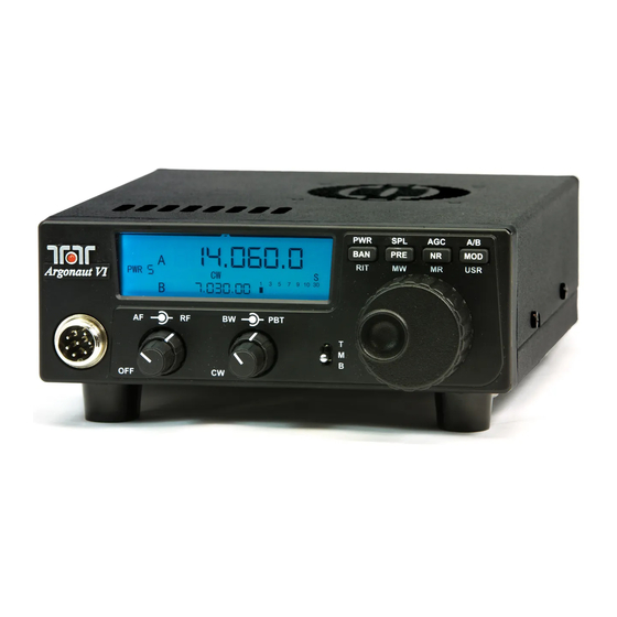
Argonaut VI Figure 1-1 539 Front Panel 1. Your new Argonaut VI 539 1.3. Accessory package 1.1. Unpacking Argonaut VI Model 539 The additional hardware and accessories listed in Table 1.3-1 come standard with your Examine the Argonaut VI transceiver for new Argonaut VI. -
Page 4: Connection To Antenna & Power Supply
1.4. Connection to Antenna & 1.5. A word about grounding Power Supply A good ground system is essential for optimum operation of any HF transmitter. The Argonaut VI is designed for use with any The best solution is to connect all the station antenna system providing a 50 Ohm resistive equipment to a single ground connection. -
Page 5: Philosophy Of Design
1.6. Philosophy of design control input. Based on the control inputs from the front panel (or remotely via the USB With the Model 539 Argonaut VI, Ten-Tec interface), writes display has created a QRP transceiver combining... -
Page 6: Easy Operation Guide
Argonaut VI Figure 2-1 539 Front Panel- (with indexes) 2. Easy Operation Guide When in transmit the bar graph meter will display your power output peaks. When you 2.1. Front Panel Indicators wish to view the SWR, ensure that the three position switch (5) labeled with TMB is in the TX/ALC LED middle (M) position, and press the MOD... -
Page 7: Front Panel Controls
Argonaut VI Figure 2-1 539 Front Panel- (with indexes) 2.2. Front Panel Controls This section provides a very brief overview of Multi Function Buttons (7, 8, 9, 10) the front panel of the Argonaut VI, more There are four buttons on the front panel to details on each control is given later in this change different operational features within manual. -
Page 8: General Operations
Argonaut VI Figure 2-1 539 Front Panel- (with indexes) 2.3. General Operations RF Gain Control (2) This section of your Argonaut VI Manual will The outer ring (2) of the AF/RF knob discuss the button operation and adjustments provides the RF Gain feature. Adjusting the common to all modes on the Argonaut VI. -
Page 9: Bw (3) Bandwidths
Argonaut VI Figure 2-1 539 Front Panel- (with indexes) BW (3) Bandwidths Band (7) Adjusting the BW control will allow you to Be sure TMB switch is in Middle position. To select the DSP filtering of your choice. This change bands or toggle through the Ham will increase the selectivity of receive and bands press the BAN button and the next helps remove close in unwanted signals. -
Page 10: Rit (7)
Argonaut VI Figure 2-1 539 Front Panel- (with indexes) Remember, AM mode will not be displayed RIT (7) or active unless EaD has been selected within the configuration menu. Be sure TMB switch is on the Bottom position. The RIT can now be toggled on and Headphones (20 on rear panel) off by pressing the RIT (7) button. -
Page 11: Recalling A Stored Memory (9)
Argonaut VI Figure 2-1 539 Front Panel- (with indexes) Storing a Frequency to Memory (8) Recalling A Stored Memory (9) To store a memory channel be sure the TMB Both mode and frequency can be stored in 1- switch is on the Bottom. Press down the MW 100 memories within the Argonaut VI. -
Page 12: Nr/Nb (9) Noise Reduction/Noise Blanker
Argonaut VI Figure 2-1 539 Front Panel- (with indexes) NR/NB (9) Noise Reduction/Noise Exit by toggling the NR button until the NR/NB or both disappear from the screen Blanker Be sure the TMB switch is in the Middle position. By pressing the NR button once you will toggle the noise blanker on. -
Page 13: Ssb Mode Operation
Argonaut VI Figure 2-1 539 Front Panel- (with indexes) 2.4. SSB Mode Operation Speech Processing (3, 5, 8) Be sure the TMB switch is in the Middle Be sure the Argonaut VI is in the USB or position. To begin SSB operation toggle the LSB mode. -
Page 14: Mic Connector
for use for mic negative signal and chassis MIC Connector ground as shown in Figure 2.4-2 Front panel jack used for connection of a microphone. The Argonaut VI features the common 8-pin microphone jack used in many amateur radio transceivers. Most dynamic or Electret Microphones can be used. -
Page 15: Mic Gain And Line Gain(10)
ALC light flickers on voice peaks when speaking into the microphone. This is the LED light within the Ten-Tec logo. Once set just press the USR (MOD) button once more to exit. To set the LINE GAIN press and... -
Page 16: Cw Mode Operation
Argonaut VI Figure 2-1 539 Front Panel- (with indexes) 2.5. CW Mode Operation CW Sidetone Frequency Ensure that the bandwidth control is rotated Setting Up CW Parameters (3,5,7,8,9,10) fully counter clockwise in the CW/Clicked Ensure that the Argonaut VI is in CW Mode. position. -
Page 17: Cw Keying And Wiring
CW Keying and Wiring 2.6. AM Mode Operation The rear panel on the Argonaut VI has a 1/8” To operate the Argonaut VI in AM mode you stereo jack for connection of a key paddle. must have the 6 KHz filter installed and you See Figure 2.5-1 for proper wiring. -
Page 18: Interfacing To A Computer For Firmware Update Mode And Pc Control/Logging Purposes
2.8. Interfacing to a computer for Firmware Update NOTE: when you plug the USB cable into a Mode and PC different USB port on the PC, it will most likely get a new COMx port number defined. Control/Logging Purposes Be aware of this when reconnecting the USB cable to the computer so that you can set it The software interface for the Argonaut VI properly in the computer program that you are... -
Page 19: Power Up Modes
Item Settings Notes: 2.9. Power Up Modes nO / none Refer to Section “60”= 6KHz “Optional Filter Configuration Menu (PWR(7)) “29”=2.9KHz Installation” for more When optional items are ordered with your “07”= 700Hz information on Argonaut VI, then these optional items will physical installation of already be installed and configured at the each filter... -
Page 20: Firmware Update Mode (A/B (10))
Firmware Update Mode (A/B (10)) 9) Select the RUF file under the Process To upgrade your transceiver, visit the TenTec Menu. web site (www.tentec.com) and download the 10) The program will update the radio and installer for the latest firmware version. A report any errors encountered. -
Page 21: Optional Filter Installation
by the way the pins and outer case 2.10. Optional Filter connect together. The ground pins will be inserted into the left holes as you face the Installation front of the radio. If your filter comes The Argonaut VI has three filter slots: Filter with the vibration barrier attached to the Slot 1 (F1), Filter Slot 2 (F2), Filter Slot 3 bottom just temporarily remove this cover... -
Page 22: Extended Feature Access Via Usb/Serial
2.11. Extended Feature Access via USB/Serial There are more features available for the Argonaut VI that are not accessible via the front panel controls. For this purpose, the USR button, MR button, and MW button are able programmed with functionality using a PC. The USB interface also permits changing various settings that cannot be mapped to front panel control buttons. -
Page 23: Argonaut Vi Rear Panel
FUSE 7.5A – DC IN ACC 1 PHONES MODEL 539 TEN-TEC, INC. SEVIERVILLE, TN MADE IN USA WWW.TENTEC.COM .5A MAX Fig 3-1 Argonaut VI Rear Panel 3. Argonaut VI Rear Panel DC OUT (16) ANT (11) The Argonaut VI is equipped with one DC... -
Page 24: Acc 1 (18)
ACC 1 (18) The Argonaut VI is equipped with an 8 pin The pin out and function are listed in the accessory connector. Refer to following following table: figure for the pin definitions as viewed from the rear panel. Pin Name / Usage Direction Line In /... -
Page 25: Keying A Linear Amplifier
Argonaut VI must use an amplifier interface 700 Hz Filter 2006 relay such as the model 318 sold through the USB/Soundcard Ten-Tec company. When using the Ten-Tec adapter Interface model 418 solid state linear (sold separately) 4 Ft DC Cable 86095... -
Page 26: Specifications
5. Specifications 5.1. Transceiver Specifications GENERAL Microphone Connector: 8-pin on front panel Headphone Jack: 1/4” stereo, accepts mono or stereo on rear panel External CW Key Jack: 1/8” stereo, accepts mono or stereo on rear panel Aux DC Output Connector: RCA 0.5A max connected to DC Power Frequency Range TX: 1.795-2.005 (160M),... - Page 27 RECEIVER SSB Sensitivity: Better than 0.7uV (0.5 Typ), 2.4Khz, 10 db SINAD, preamp off AM Sensitivity: Better than 4 uV, (2.0uV Typ) 30% Mod, 6Kh BW, 10 dB SINAD, preamp off Selectivity IF1: 2.9khz standard, 9.0018 MHz, 2 optional filter positions Selectivity IF2: 30 KHz Lowpass filter Selectivity, DSP IF:...
- Page 28 TRANSMITTER RF Power Output: Adjustable, 1-10 W, +/- 1 dB CW, SSB, AM, AFSK,PSK Duty Cycle: 100% for up to 10 minutes @ 10 watts CW/SSB TX Bandwidth: 2.9kHz Filter AM TX Bandwidth: 6kHz Optional Filter Microphone Input Impedance: >10 k-ohms at 1 kHz Microphone Sensitivity: 1 mV RMS for full power output, internal gain adjustment, 9v dc power for electret elements...
-
Page 29: Transceiver Block Diagram
5.2. Transceiver Block Diagram 539 / Argonaut VI Users manual Release 0.10 – November 13, 2012 Part #74479 Printed in USA... -
Page 30: Fcc Compliance
• Connect the equipment into an outlet on a circuit different from that to which the receiver is connected. • Consult Ten-Tec service for technical assistance (865) 428-0364 NOTE: THE GRANTEE IS NOT RESPONSIBLE FOR ANY CHANGES OR MODIFICATIONS NOT EXPRESSLY APPROVED BY THE PARTY RESPONSIBLE FOR COMPLIANCE. -
Page 31: In Case Of Difficulty
6. In Case of Difficulty While we cannot cover every possible Problem: Distorted SSB transmit – or – problem, here are some hints for dealing with Perceived RFI in the shack. some potential difficulties. Check the Be certain the mic gain is set properly. The obvious. - Page 32 Problem: Transceiver power shuts off Manager. It is possible that the USB port was while transmitting used previously and for some reason The Argonaut VI is equipped with a silicon- Windows has not released it for use. In this controlled rectifier that opens if the PA instance, disconnect the USB cable at either current draw exceeds an instantaneous power the computer end or the Argonaut VI end, exit...
-
Page 33: Warranty & Return Policy
7. Warranty & Return Policy Warranty policy for Ten-Tec products is covered in the gold color page located on the last page of this manual. FOR EQUIPMENT MANUFACTURED BY TEN-TEC: Ten-Tec factory built radio equipment is sold under a 30-day risk-free trial period. Any piece of equipment manufactured by Ten-Tec may be returned, undamaged, within 30 days of purchase for a full purchase price refund, less shipping charges (customer pays shipping both ways).
Need help?
Do you have a question about the Argonaut VI 539 and is the answer not in the manual?
Questions and answers