Advertisement
Quick Links
Q U I C K I N S T A L L G U I D E - E N
Installing the Enphase Communications Kit 2 INT
The Enphase Communications Kit 2 INT (COMMS-KIT-INT-02) enables wired communication between IQ Gateway Metered and IQ Battery 5P using control
(CTRL) cables.
Read and follow all warnings and instructions in this guide. Do not proceed if you do not fully understand any of the concepts, terminology, or hazards
outlined in these instructions. These instructions are not meant to be a comprehensive guide to installing an IQ Battery 5P system. Use the IQ Battery 5P
quick install guide and this document to plan your installation. All installations must comply with local codes and standards.
✓
NOTE: Scan the QR code for the latest QIG (and multi-language QIGs):
Link:
https:/ /link.enphase.com/commskit2-install-guide-eu
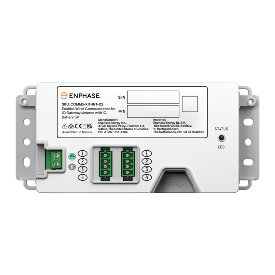
Figure 1: Front view of the Communications Kit 2 INT
Contents
The Enphase Communications Kit 2 INT enables the IQ Gateway Metered
to communicate with the IQ Battery 5P. The device has a USB Type-C
port, two control cable ports, and a drain port.
The Communications Kit 2 INT includes the following accessories:
•
One control header with the termination resistor
•
One control header without a resistor
•
One 400 mm USB Type-C to USB Type-A cable with a 200 mm
right-angled USB Type-A to Type-A adaptor
•
Zip-ties for cable management
•
DIN rail adapters and screws
•
Two spare control headers
The USB port connects the Communications Kit 2 INT to the
IQ Gateway (either USB port on the IQ Gateway can be used). This
enables communication between the device and the IQ Gateway.
The control headers must be installed on the control ports on the
Communications Kit 2 INT.
© 2024 Enphase Energy. All rights reserved. Enphase, the e and CC logos, IQ, and certain other marks listed at
https:/ /enphase.com/trademark-usage-guidelines
countries. Data subject to change. 2024-07-10
1
(Model: COMMS-KIT-INT-02)
are trademarks of Enphase Energy, Inc. in the U.S. and other
Installation
DANGER! Risk of electric shock. All sources to equipment
being serviced must be disconnected external to the device.
Storage circuits must ALWAYS be isolated via a circuit breaker
or isolator switch before working on any part of the system.
Installation and commissioning
1
A ) Install the Communications Kit 2 INT in an IP54 or higher-rated
enclosure with adequate space for cable routing. It is recommended
to install both the IQ Gateway and the Communications Kit 2 INT in the
same enclosure.
B ) The enclosure should have access to an earth terminal bar.
C ) Based on your installation design, identify if the
Communications Kit 2 INT is a terminating node or a non-terminating
node in the daisy chain of devices connected through a control cable on
the site. The installation procedure varies accordingly, as described later
in the document.
D ) Ensure the system is powered off before you begin the installation.
E ) Ensure that you have these tools and materials for the installation:
a. Torque terminal screwdrivers and wire stripper
b. Control cables
F ) Plug in the wired control headers to the unit. Refer to section 2,
Wiring the Communications Kit 2
G ) Connect the cable from the earth bar to the PE port on the device. This
is only required if connecting the drain wire of the control cable to the
drain wire port on the Communications Kit 2 INT.
H ) Connect the device to an IQ Gateway Metered with the USB cable
provided.
I ) Switch on the IQ Gateway Metered.
✓
NOTE: The Communications Kit 2 INT can be installed in two ways. The
box ships with DIN rail adapters that can be connected to the device to
mount it on a DIN rail. The device can also be screwed into the back
wall of the enclosure using the screw points provided on extreme
ends on either side of the unit.
Cable torque details are given as follows:
CA B LE TY PE
W IR E S IZE
Control cables
0.34 mm
Earth cables
0.75 mm
Comms-Kit-2-QIG-140-00503-01-EN-AU-2024-07-10
INT.
TORQU E
2
0.2 N m
0.2 N m
2
Advertisement

Related Manuals for enphase Communications Kit 2 INT


Summary of Contents for enphase Communications Kit 2 INT
- Page 1 (Model: COMMS-KIT-INT-02) Installing the Enphase Communications Kit 2 INT The Enphase Communications Kit 2 INT (COMMS-KIT-INT-02) enables wired communication between IQ Gateway Metered and IQ Battery 5P using control (CTRL) cables. Read and follow all warnings and instructions in this guide. Do not proceed if you do not fully understand any of the concepts, terminology, or hazards outlined in these instructions.
- Page 2 Control (CTRL) wiring between system components Control wiring guidance for installing IQ Battery 5P(s) with a Communications Kit 2 INT: Refer to the following wiring sequences to understand the position of the header with termination resistor, wiring order, and drain wire termination location.
- Page 3 Sequence 1: IQ Battery 5P(s) - Communications Kit 2 INT To earth bar* Termination resistor Termination resistor earth bar Sequence 2: IQ Battery 5P - Communications Kit 2 INT - IQ Battery 5P To earth bar* Termination Termination resistor resistor earth bar...
- Page 4 Settings tab in the Enphase Installer App and tap the Update Now button under IQ Gateway Software. Note for third-party products C ) Follow the steps in the Enphase Installer App to go through the Any third-party manufacturer or importer of product(s) used to install or commissioning process.
Need help?
Do you have a question about the Communications Kit 2 INT and is the answer not in the manual?
Questions and answers