Table of Contents
Advertisement
Quick Links
Advertisement
Table of Contents

Related Manuals for Eaton PFS02


Summary of Contents for Eaton PFS02
- Page 1 PFS02 Particle Flow Sensor Operating manual Version 1.0 Rev.-date: 13.05.2024...
-
Page 2: Table Of Contents
Contents SAFETY INFORMATION 1.1. Signal glossary ....................5 1.2. Symbole ......................5 1.3. Terms ......................... 5 1.4. Abbreviation ...................... 6 SAFETY INSTRUCTIONS 2.1. About this chapter ..................... 6 2.2. Intended use ...................... 6 2.3. Improper use ...................... 6 2.4. Reasonably foreseeable misuse ..............7 2.5. - Page 3 11.3.2. Alarm memory....................20 11.3.3. Low-pass filter ....................20 11.4. Configuration analog..................21 11.5. Standard ......................21 11.6. Configuration flow ................... 22 11.6.1. Automatic ...................... 22 11.6.2. Fix ......................... 22 11.7. Communication ....................22 11.7.1. Type ......................22 11.8. Baud rate CAN ....................22 11.8.1.
- Page 4 17.1.1. Contamination classesaccording to ISO 4406:17 .......... 49 17.1.2. Contamination classes SAE AS 4059E ............50 17.1.3. Contamination classes according to NAS 1638 ..........50 17.1.4. Contamination classes according to GOST 17216 ........51 18. MAINTENANCE AND REPAIR 18.1. Maintenance ..................... 53 18.2.
-
Page 5: Safety Information 5 1.1. Signal Glossary
Safety information This documentation is applicable for the particle monitor PFS02. This documentation is written for service engineers, technicians, operators and system operators. This document contains important information for safe and appropriate assembly, transport, activation, operation, usage, servicing, dismantling and simple troubleshooting. -
Page 6: Abbreviation
(functional safety). Eaton Technologies GmbH assumes no liability for damages resulting from improper use. The risks associated with improper use are solely with the user. -
Page 7: Reasonably Foreseeable Misuse
Product and technology related safety instructions Laser The PFS02 Particle Flow Sensor contains a laser sensor that is classified for intended use as a class 1 laser according to DIN EN 60825-1:2001-11. In reasonably foreseeable circumstances, the accessible laser radiation is not dangerous. -
Page 8: Indications On The Product
For prevention of material damage and product damage Danger due to improper handling! Material damage! The PFS02 may only be used in accordance with Section 2.2 Intended use. Leakage or spillage of hydraulic fluid! Environmental pollution and ground water pollution! ... -
Page 9: Scope Of Delivery
5.1. Functional description The PFS02 is an optical particle monitor operating on the principle of light extinction. It consists of a flowed measuring cell (A), a laser (B) and a photo diode (C). The laser beams through the measuring cell to the opposite photo diode. If a particle passes through the laser beam, the light intensity detected by the photo diode is reduced. -
Page 10: Component Overview
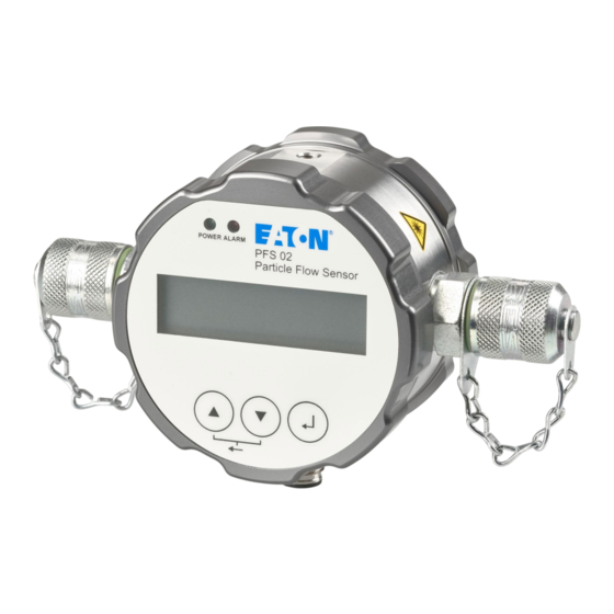
5.2. Component overview 1. Hydraulic connection fluid 2. Front panel and display 3. Inidcator light „Power“ 4. Inidcator light „Alarm“ 5. Display 6. Hydraulic connection Fluid 7. Selection button [ 8. Button DOWN [] 9. Connection M12x1 sensor cable 10. -
Page 11: Identification Of The Product
Changing of values: With the button UP [] or the button DOWN [] the required parameter can be marked in the menu structure. To choose this parameter press the selection button, then the value can be changed with the UP [] or DOWN [] button. Changes are confir- med by pressing the selection button after the last position of input ability. - Page 12 The Minimess connections can be exchanged by other connectors. A maximum tightening torque of 25 Nm shall not be exceeded. While exchanging the connection couplings, no dirt, chips or other contaminations shall enter the interior of the device. Avoid blind holes in the supply line. The device should be installed at a relevant measurement location in the hydraulic circuit where constant pressure conditions exist.
-
Page 13: Mounting
7.3. Mounting The device has two options for mounting: Orientation Mounting Tightening torque Screw depth Bottom 4 x M5 Max. 4 Nm (strength class 8.8) Min. 5 Laterally 2 x M6 Max. 8 Nm (strength class 8.8) Min. 6 7.4. Mechanical stress The mechanical stress on the device must not exceed the data given in the table below. -
Page 14: Pin Assignment (View From Above)
Danger to life – risk of injury Only a qualified electrician should install the device. Comply with national and international guidelines for setting up electrical equipment. Power supply in accordance with EN50178, SELV, PELV, VDE0100-410/A1. De-energize the system for installation and connect the device as follows: A shielded sensor cable must be used. 8.1. -
Page 15: Start Screen
Start screen The condition of the device is visible on the start screen. Status display Time display in hh:mm:ss Status display No time given Displayed Ordinal numbers for standard 4/6/14/21µm 10.1. Status display Running measurement Regulating laser (flashing) at the start of each measurement for 2 to 3 seconds Device in pause mode 10.2. -
Page 16: Menu And Operation
Menu and operation The [▲] or [▼] buttons are used to navigate in the menu and to scroll through the entries. Press the select button [ ] to jump to the next level. Go back by pressing the [▲] and [▼] button simultaneously. -
Page 17: Menu Structure
11.1. Menu structure... -
Page 18: Operating Modes
) and better (according to ISO 4406), the measuring time should be at least 120 seconds. Standard setting for the measuring time is 60 seconds. 11.2.1. Time-controlled measurement The PFS02 works with the set measuring time and pause times between measurements. The following settings are to be observed: Parameter Min. -
Page 19: Automatic
After the end of a measurement, the measuring result is shown on the start screen. The compliance with the recommended measuring times needs to be ensured. Information regarding time specification on the start screen: Running measurement: Elapsed time (up counter) Pause mode: Displays the measuring time of the last measurement (static display) 11.2.4. -
Page 20: Filter Mode
11.3.3. Low-pass filter In a hydraulic system short-term increases in concentration (peaks) may arise, which are not representative for the overall system, e.g. by operating a manual valve. The PFS02 detects these changes and displays them correctly. The low-pass filter ensures that when an alarm is set according to chapter 11.3.1.1 and 11.3.1.2, it is not triggered at each peak. -
Page 21: Configuration Analog
The following diagram shows a step response for various values of the low-pass filter. The table shows how many measurements have to be carried out, so that the internal concentration for alarm evaluation reaches 90% of the actual measured concentration. Low-pass filter values Number of measurements up to 90%... -
Page 22: Configuration Flow
11.6. Configuration flow 11.6.1. Automatic In addition to the particle size and number of particles, the PFS02 also calculates a volume flow index to be able to evaluate the particle concentration. The calculated flow rate index is not an exact measurement of the volume flow. It is an internal calculation value, which may be used as an indicator during installation and commissioning of the unit. -
Page 23: Node Id Can
125 BAUD 250K BAUD 500K BAUD 1000K BAUD TERM. CAN With the activation of „TERM. CAN“, the transmission line in the device will be completed with a terminating resistor of 120 Ohm. 11.8.1. Node ID CAN The Node ID is the address, with which the device can be addressed via the CAN bus. The Node ID is required for CANopen and CAN J1939 protocol. -
Page 24: Sensor Parameter
11.10. Sensor parameter 11.10.1. Measurement results Represenation of the results of the last valid measurements. With the UP [▲] and DOWN [▼] button all results are displayed to one measurement. With the enter key [ ] the previous measurement results can be displayed again. The representation of the ordinal numbers varies with the selection of the standard. -
Page 25: Error Info
11.10.4. Error info The PFS02 collects various errors, information and operating status and summarizes them into four 16 bit values, the ERC (Error Code). These are always shown in hexadecimal notation. For further information on the decoding see Chapter 24.2 Coding error bits. -
Page 26: Calibration
An acknowledgement is not possible. CALIBRATION NECESSARY Resetting the calibration note on the display can only be carried out by Eaton Technology service. The remaining hours until the appearance of the first message can be retrieved in the device... -
Page 27: Analog Current Output (4
Analog current output (4…20mA) 13.1. Measurement without load resistance The measurement of the current should be carried out with a suitable ammeter. Pin 6 Pin 8 The ordinal numbers for the various standards are calculated according to the tables in chapter 13.2. -
Page 28: Sequential Data Output For Iso 4406:17 And Sae As 4059E
Standard Formula ordinal number ISO 4406 1,625 x I[mA] – 6,5 SAE AS 4059 E 0,875 x I[mA] – 5,5 NAS 1638 I[mA] – 5 GOST 17216 2 x I[mA] - 9 NAS and GOST are only available from software version 2.00.15. 13.5. -
Page 29: Switching Output
14.2. Switching output The appearance of an alarm can be detected next to the red LED and the warning triangle on the display on the alarm output at pin 7. See Chapter 11.3 Alarm configuration. Two options are available. Pin 7 is not a switch in the sense of a turnkey. Depending on the state of alarm, pin 7 is on the ground (L-) or it is not connected (floating). -
Page 30: Communication Rs232
= 0,5A Communication RS232 The PFS02 has a serial interface, via which it can be read out and configured. For this purpose, a PC and an appropriate terminal program or a readout software is needed. The sensor has to be connected to a free COM port of a computer. A suitable communication cable for serial connection between sensor and computer / controller is described in Chapter 20 Accessories. - Page 31 Checksum RMemS[CR] Number max. records in memory MemS:%d[-];CRC:z[CR][LF] RMemU[CR] Number of current records in memory MemU:%d[-];CRC:z[CR][LF] RMemO[CR] Memory organization: Time; ISO4um; ISO6um; ISO14um; ISO21um; SAE4um; SAE6um; SAE14um; SAE21um; NAS; GOST; Conc4um; Conc6um; Conc14um; Conc21um; FIndex; MTime; ERC1; ERC2; ERC3; ERC4[CR][LF] RMem[CR] Reading of all records in memory [Speicherorganisation]...
-
Page 32: Configuration Commands
15.3. Configuration commands Instruction format Specification Return format Measuring time in seconds Write WMtime%d [CR] %d = 30…300 Mtime:%d[s];CRC:z[CR][LF] Default: 60 Read RMtime[CR] Pause time in seconds Write WHtime%d[CR] %d = 1…86400 Htime:%d[s];CRC:z[CR][LF] Default: 10 Read RHtime[CR] Operating mode Write SStartMode%d[CR] %d = 0: time-controlled measurement StartMode:%d;CRC:z[CR][LF] (default) - Page 33 Instruction format Specification Return format Limit value alarm ISO/SAE 6µm (depending on set standard) Write WAlarm6%c[CR] Alarm6:%c[-];CRC:z[CR][LF] ISO: %c = 0…28 0 = Alarm deactivated Default: 0 SAE: %c = 000…12 000 = Alarm deactivated Default: 000 Read RAlarm6[CR] Limit value alarm ISO/SAE 14µm (depending on set standard) Write WAlarm14%c[CR] ISO: %c = 0…28...
-
Page 34: Checksum Calculation (Crc)
Instruction format Specification Return format Low-pass filter Write WMean%d[CR] %d = 1...255 Mean:%d[- ];CRC:z[CR][LF] 1 = no Filter Default: 2 Read RMean[CR] Communikation type Write SComMode%d[CR] ComMode:%d;CRC:z[C %d = 0: RS232 (default) R][LF] %d = 1: CANopen %d = 2: Autodetect %d = 3: CAN J1939 Read Siehe Antwort: "RCon"... -
Page 35: Communication Can
Including Line feed [LF] and Carriage Return [CR]. If the result is dividable through 256, the transmission is error-free. An example of the response of the PFS02 to the command „RMemS[CR]“ is shown below. (Reading out the memory usage) „RmemS[CR]“... -
Page 36: Canopen
20 kbit/s 2500 m 10 kbit/s 5000 m 16.1. CANopen The CANopen protocol defines what is described, not the way something is described. With the implemented methods, a distributed control network is realized which can connect everything, from very simple participants to very complex controllers without causing communication problems between the participants. -
Page 37: Canopen Communication Objects
2000 - 5FFF Communication Profile Area (manufacturer-specific) 6000 - 9FFF Device profile-specific Device Profile Area (e.g. “DSP-401 Device Profile for I/O Modules”) A000 - FFFF Reserved 16.1.2. CANopen Communication Objects Communication objects transferred with CANopen are described by services and protocols and are classified as follows: Network Management (NMT) provides services and is used for bus initialization, error handling and node control... - Page 38 The sensor can only function as a server, it only responds to SDO messages and does not spontaneously send any queries to other participants The ID of the SDO messages from the sensor to the client is NodeID+0x580. The expected ID for requests from the client to the sensor (server) in the case of SDO messages is NodeID+0x600.
-
Page 39: Process Data Object (Pdo)
CAN-ID Index Subidx SDO user data COB-ID 11 CANopen Message from 0xBB 0x0D 0x03 0x00 0x580 + 0x08 0x43 0x18 0x10 0x04 client to sensor NodelD An example of the data upload (heartbeat time) via SDO to the sensor object dictionary at index 0x1017 with a data length of 16 bits is shown below. -
Page 40: Pdo Mapping
16.1.5. PDO Mapping The sensor supports three to four transmit PDOs (TPDOs) to allow the most effective operation of the CAN-bus. The sensor does not support dynamic mapping of PDOs, the mapping parameters are therefore only readable but not writeable. The next figure shows the principle of the mapping of objects from the OD in a TPDO, it corresponds to CiA DS-301, Chapter 9.5.4. - Page 41 Complete OD, with map-enabled objects Index Type Object TPDO2 mapping parameter in OD, at Index 0x1A01 Type Value 2000 Operating hours stamp U 32 20000220h 2002 SAE4µm U 32 20020108h U 32 20020208h 2002 SAE6µm U 32 2020308h U 32 20020408h 2002 SAE14µm...
-
Page 42: Canopen Object Dictionary" In Detail
The complete object dictionary is represented in the following table. With few exceptions, the possible settings correspond to the CANopen Standard as described in DS 301. Suitable EDS files for the sensors are available on the homepage of Eaton Technologies GmbH. mapped... - Page 43 mapped SIdx name type Attr. default notes on PDO event timer unsigned 16 1F4h event timer in ms for asynchronous TPDO3 range: 0..65000 transmit PDO4 1803h record parameter number of entries unsigned 8 largest sub index COB-ID unsigned 32 COB-ID used by PDO, 480h+ range: 481h..4FFh, can be NodeID...
- Page 44 mapped SIdx name type Attr. default notes on PDO PDO mapping for 1st unsigned 32 20000120h operating hours, 4 Byte app obj. to be mapped PDO mapping for 2nd unsigned 32 20030108h oil condition bits, 1 Byte app obj. to be mapped PDO mapping for 3rd unsigned 32...
- Page 45 mapped SIdx name type Attr. default notes on PDO SAE6µm unsigned 8 SAE14µm unsigned 8 SAE 21µm unsigned 8 condition 2003h array monitoring bits number of entries unsigned 8 largest sub index oil specific bits unsigned 8 concentration limit exceeded flow high flow low measurement not...
- Page 46 mapped SIdx name type Attr. default notes on PDO GOST 17216 unsigned 8 offset of one to display 00 and 0 0 == GOST 00 1 == GOST 0 2 == GOST 1 ………… 17 == GOST 16 (maximum value) 1 = start of a measurement 2 = stop of a measurement 2020h...
-
Page 47: Can J1939
Function available only from software version 2.00.15. Classification systems The automatic particle counter (APC). which is used for the calibration of the PFS02 is primary calibrated according to ISO 11171. The ordinal numbers of the PFS02 are displayed according to ISO 4406. these are determined by the measured particle concentration for 4. -
Page 48: Definition Of Particle Sizes
17.1. Definition of particle sizes In industrial hydraulics, the particle numbers are coded according to ISO 4406. With the replacement of the test dust ACFTD by ISO MTD, the particle sizes have been redefined. ACFTD particle size ISO MTD particle size definition (ISO 4402:1991) definition (ISO 11171) Partikel... -
Page 49: Contamination Classesaccording To Iso 4406:17
17.1.1. Contamination classesaccording to ISO 4406:17 The values are added in cumulated form (all particles >4 µm. all particles > 6 µm. …). Concentration in particles / ml ISO 4406:17 Display PFS02 From up to and including 2.500.000,00 > 28 1.300.000,00... -
Page 50: Contamination Classes Sae As 4059E
The NAS 1638 is divided into different size classes. 5-15µm, 15-25µm, 25-50µm, … The particles are counted differentially and not accumulated as in ISO 4406. The PFS02 can only measure the sizes 4, 6, 14, 21 µm. Therefore, the cleanliness class is calculated only based on NAS 1638. -
Page 51: Contamination Classes According To Gost 17216
The GOST 17216 is divided into different size classes. 5-15µm, 15-25µm, 25-50µm, … The particles are counted differentially and not accumulated as in ISO 4406 The PFS02 can only measure the sizes 4, 6, 14, 21 µm. Therefore, the cleanliness class is calculated only based on GOST 17216. -
Page 52: Maintenance And Repair
Damage to the hydraulic system and the seals The water pressure of a high-pressure cleaner can damage the hydraulic system and the seals of the PFS02. The water displaces the oil from the hydraulic systems and the seals. Do not use a high-pressure cleaner for cleaning. -
Page 53: Maintenance
Repair to the PFS02 may only be carried out by the manufacturer or authorized distributors and subsidiaries. There is no guarantee for self-initiated repairs. Decommissioning, disassembly, disposal The PFS02 is a component which does not have to be taken out of operation. Therefore, this chapter does not contain any information. Incorrect disassembly If the particle monitor is disassembled incorrectly during pressurization, there is a risk of leakage of media under high pressure. -
Page 54: Accessories
Accessories Description Article number Data cable for computer connection 356452 Side 1: M12 8-pole, 90° angled, IP67 Side 2: D-Sub-plug 9-pole with additional coaxial power connector for power supply Length: 5m, shielded Temperature area -25 °C…90 °C Oil-resistant Datenkabel with open ends 356453 Side 1: M12 8-pole, 90°... -
Page 55: Faq
Measuring cell contaminated Clean PFS02 using clean oil or a solvent (symbol [►] flashes in display) (e.g. isopropanol) Rinse with clean oil in the opposite direction Measuring cell defective Please contact Eaton Service (symbol [►] flashes in display) - Page 56 Is the device compatible with diesel fuels? Yes, the device is compatible. Is the device compatible with phosphate ester / The standard version of the PFS02 is not skydrol resistant. skydrol? Can CAN and RS232 be used in parallel? No, there is only the possibility of applying one type of commu- nication.
-
Page 57: Technical Data
Technical data 23.1. Technical data Max. operating pressure: 420 bar Permissible flow rate: 50…400 ml/min Temperature: -20…85 °C Rel. humidity (not condensing): 0…100 % r.H. Display readable up to: 60 °C Compatible fluids: Mineral oils (H, HL, HLP, HLPD, HVLP), synthetic esters (HETG, HEPG, HEES, HEPR), polyalkylenglycols (PAG), zinc and ash-free oils (ZAF),... -
Page 58: Dimensional Drawing
23.2. Dimensional drawing Appendix 24.1. Cable lengths The tables show the maximum cable lengths for different transmission rates. Baud rate Max. cable lengths 9600 150 m 19200 15 m 57600 115200 < 2 m... -
Page 59: Coding Error Bits
24.2. Coding error bits Every ERC is displayed in hexadecimal notation and consists of four characters (0-F). The conversion for each character is based on the following tables. hexadecimal binary 0000 0001 0010 0011 0100 0101 0110 0111 1000 1001 1010 1011 1100... - Page 60 Bit 1 Laser current too small → Bit 3 Detector voltage too high → Bit 5 Temperature < -20 °C → Bit 12 = 1 Alarm mode = filter →...
- Page 62 Tel: +65 6825-1620 others is beyond our control, no guarantee, expressed or Friedensstraße 41 implied, is made by Eaton as to the effects of such use or 68804 Altlußheim, Germany the results to be obtained. Eaton assumes no liability arising out of the use by others of such products. Nor is the...
Need help?
Do you have a question about the PFS02 and is the answer not in the manual?
Questions and answers