
Related Manuals for Eaton URTDII


Summary of Contents for Eaton URTDII
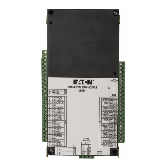
- Page 1 Instruction Leaflet IL02602013E Effective November 2010 Universal Resistance Temperature Detector Module II Table of Contents 1.0 Introduction 2.0 Assembly Drawing 3.0 Installation 4.0 Communications...
- Page 2 122 meters (400 feet) from the protective device when using the fiber optic link. The URTDII can be used to monitor as many as 12 RTD The URTDII can also be used as a stand-alone device inputs, These inputs fall into four groups that consist of: six that communicates on a Modbus network.
- Page 3 3.1 Programming the Universal RTD Module II This industrial type control should be installed, operated and The URTDII must be programmed for the type of RTDs that maintained by adequately trained personnel. The instruc- are being monitored. A DIP switch assembly on the module tions in this document do not cover all details, variations, enables programming for the specific application.
- Page 4 10 Ohm Copper 3.2 RTD Wiring 3.3 Wire Routing Each RTD must be wired to the URTDII, as shown in Figure Wire routing is divided into two types: High voltage (440 4. The following guidelines must be observed: Vac and higher) and low voltage (120 Vac and DC signals).
- Page 5 DO NOT CONNECT CABLE'S SHIELD WIRE AT THIS END! USE TAPE TO INSULATE otee: Each shielded cable conductor must be connected on the URTDII as shown. Use of three-lead RTDs is recommended. RTDs must not be grounded at the motor, and no common connections between RTDs should be made at the motor.
- Page 6 RTDs must not be grounded at the motor and no common connections between individual RTDs should be made at the motor. Figure 5, Wiring to URTDII IL02602013E - November 2010 - www.eaton.com...
- Page 7 AC Power Supply DC Power Supply Line Positive Neutral Negative 3.5 Control Power Connect the power supply terminals (labeled J10A) on the URTDII to a suitable power source. Refer to Table 4 for con- nection guidelines. IL02602013E - November 2010 - www.eaton.com...
- Page 8 Modbus system. If this address ing module with a URTDII module, dipswitch 11 selects a is selected it will put the URTDII module in a mode legacy mode that provides data in the same format as the provided exclusively for IMR systems.
- Page 9 Dipswitches 11 and 12 of dipswitch S1 (accessed on the The following tables show the addresses and data values side of the URTDII) set the Modbus baud rate. Table 7 contained in each application category with a base address shows the setting definitions: of 0x00.
- Page 10 November 2010 Eaton Corporation 1000 Cherrington Parkway Moon Township, PA 15108-4312 Tel. 1--800-809-2772, Option 4 www. Eaton.com © 2010 Eaton Corporation PowerChain Management is a registered All Rights Reserved trademark of Eaton Corporation. Printed in USA Publication No. IL02602013E All other trademarks are property of their November 2010 respective owners.
Need help?
Do you have a question about the URTDII and is the answer not in the manual?
Questions and answers