
Related Manuals for VWR DO40-5


Summary of Contents for VWR DO40-5
- Page 1 DO40-5 Dissolved oxygen measuring device Operating manual European catalogue number: EU connection: 664-0234 Version: 1.0 Issued: 07.01.2019...
-
Page 2: Table Of Contents
Table of contents Table of contents Legal address of the manufacturer.................... 4 About this documentation ......................... 5 Foreword............................... 5 Purpose of the document........................ 5 Warranty ............................... 5 Compliance with local laws and other legal regulations ............... 5 Correctness of content.......................... 6 Layout of this document........................ - Page 3 Table of contents Configuration ............................ 22 8.2.1 Explanation ............................ 22 8.2.2 Opening the configuration menu...................... 22 8.2.3 Configuring parameters of the configuration menu................ 23 8.2.4 Adjustment of the measuring input ..................... 24 8.2.5 Configuring parameters of the adjustment menu................ 25 Error and system messages......................
-
Page 4: Legal Address Of The Manufacturer
1 | Legal address of the manufacturer DO40-5 1 Legal address of the manufacturer VWR International bvba Researchpark Haasrode 2020 Geldenaaksebaan 464 B-3001 Leuven Phone: + 32 16 385011 http://be.vwr.com 4 / 32 B-H86.0.21.DB201-1.0... -
Page 5: About This Documentation
VWR guarantees that this product will remain free from material and production de- fects for a period of two (2) years from the time of delivery. If there is a defect, VWR shall decide on its own discretion whether to repair or replace the product free of charge or to provide the customer with a refund of the purchase price of the product, insofar as it is sent back during the warranty period. -
Page 6: Correctness Of Content
2 | About this documentation DO40-5 2.5 Correctness of content The contents of this document were checked for corrected and are subject to a con- tinuous correction and updating process. This does not rule out potential errors. In the event that errors are discovered or in case of suggestions for improvement, please in- form us immediately via the indicated contact information in order to help us make this document even more user-friendly. - Page 7 DO40-5 About this documentation | 2 NOTE For information about the software version, press and hold the ON button to switch on the product for longer than 5 seconds. The series is shown in the main display and the software version of the product is shown in the secondary display.
-
Page 8: Safety
3 | Safety DO40-5 3 Safety 3.1 Explanation of safety symbols DANGER This symbol warns of imminent danger which can result in death, severe bodily injury, or severe property damage in case of non-observance. DANGER This symbol indicates danger for living tissue as well as a variety of materials, which can be damaged or destroyed when coming into contact with this chemical. -
Page 9: Safety Instructions
DO40-5 Safety | 3 DANGER Incorrect area of application! In order to prevent erratic behaviour of the product, personal injury or property dam- age, the product must be used exclusively as described in the chapter Description [} p. 11] in the operating manual. -
Page 10: Intended Use
3 | Safety DO40-5 For this purpose, also refer to 2 Technical data [} 29] 3.4 Intended use The product is designed for analysis of the oxygen concentration and/or oxygen satur- ation in freshwater and salt water. It is used, for example, for the monitoring of wells, sewer lines and aquaria. -
Page 11: Description
DO40-5 Description | 4 4 Description 4.1 Scope of delivery Please check to ensure the completeness of the product after opening the package. You should find the following components: – Quick reference guide – Handheld measuring device, ready for operation, including batteries –... -
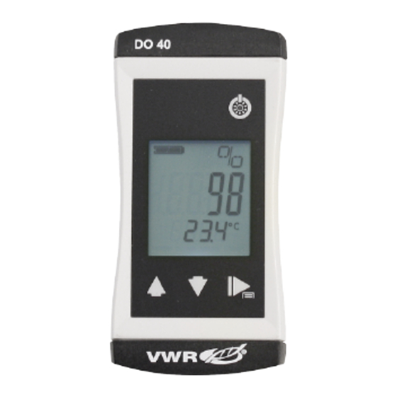
Page 12: The Product At A Glance
5 | The product at a glance DO40-5 5 The product at a glance 5.1 The DO40-K LCD Display DO40-K DO40K 5.2 Display elements Display Battery indicator Evaluation of the battery status Unit display Display of units, if applicable, with unstable symbol... - Page 13 DO40-5 The product at a glance | 5 Long press Reset the min/max value of the current measure- ment Both simultaneously Rotate display, overhead display Function key Press briefly Freeze measurement Return to measurement display Call up next parameter Long press, 2s...
-
Page 14: Bases For Measurement
6 | Bases for measurement DO40-5 6 Bases for measurement 6.1 Oxygen sensor 6.1.1 Explanation The oxygen sensor is an active sensor. It consists of a platinum cathode, a lead anode and potassium hydroxide (KOH) as an electrolyte. If oxygen is present, it is reduced on the platinum cathode and the sensor delivers a signal. -
Page 15: Design
DO40-5 Bases for measurement | 6 6.1.2 Design Refill opening Shaft Membrane head Platinum electrode Storage bottle Platinum electrode If oxygen is present, it is reduced on the platinum electrode and the sensor delivers a signal. Soiling on the platinum electrode or between the membrane and electrode can influence the measurement. -
Page 16: Operating Position
6 | Bases for measurement DO40-5 – Mechanical stress of the sensor membrane – Storage in dry air – Continuous use in elevated carbon dioxide concentrations 6.1.4 Operating position The oxygen sensor should be arranged vertically upwards with the connecting cable. -
Page 17: Environmental Pressure, Water Depth And Air Pressure
DO40-5 Bases for measurement | 6 ter; the value is 0. A salinity of approx. 35 PSU is normal for sea water. The salinity correction is adjusted to aqueous media having a chemical composition corresponding to sea water. The International Oceanographic Tables (IOT) are used as a basis for the correction. - Page 18 6 | Bases for measurement DO40-5 3. Fill the pipette with the KOH electrolyte and initially fill the membrane head to ¾ full. Rinse off the excess electrolyte. 4. Slowly fill the sensor via the fill opening. In the process, tilt the sensor from side to side and tap the shaft to force out air bubbles.
-
Page 19: Maintenance
DO40-5 Maintenance | 7 7 Maintenance 7.1 Operating and maintenance notices NOTE If the product is stored at a temperature above 50 °C, or is not used for an extended period of time, the batteries must be removed. Leaks from the batteries are avoided as a result. -
Page 20: Calibration And Adjustment
7 | Maintenance DO40-5 – Use new, high-quality batteries! – Do not use different types of batteries! – Remove depleted batteries and dispose of them at a suitable collection point! NOTE Unnecessary screwing places the water-tightness of the product, among other things, at risk and should be avoided. - Page 21 DO40-5 Maintenance | 7 Unscrew the lid of the storage bottle and only position it so that a small exchange of air and pressure equalisation can take place Instruction 1. Place the electrode in the calibration container. If necessary, wait until the temper- ature has equalised and a stable value has been achieved.
-
Page 22: Operation
8 | Operation DO40-5 8 Operation 8.1 Commissioning 8.1.1 Explanation Description The product is switched on with the On/Off button. It may be necessary to configure the product after switching on. See Configuration [} p. 22]. Prerequisite – Sufficiently full batteries are inserted in the product. -
Page 23: Configuring Parameters Of The Configuration Menu
DO40-5 Operation | 8 4. When you have selected the desired parameter, change the parameter to the de- sired value with the Up button and the Down button. 5. The changes are saved after running through the entire Configuration menu. STOR appears in the display. -
Page 24: Adjustment Of The Measuring Input
8 | Operation DO40-5 Shut-off time POFF No automatic shut-off Automatic shut-off after a selected time in minutes, 15 30 60 120 240 during which no buttons have been pressed Backlighting L,TE Backlighting deactivated 15 30 60 120 240 Automatic shut-off of the backlighting after a selec-... -
Page 25: Configuring Parameters Of The Adjustment Menu
DO40-5 Operation | 8 4. When you have selected the desired parameter, change the parameter to the de- sired value with the Up button and the Down button. 5. In order to save the new parameter value, press and hold the Function key for longer than 1 second. - Page 26 8 | Operation DO40-5 – Display in ice water setpoint T.OF = 0.0 °C – Display in water bath 36.6 °C – Display in water bath setpoint T.SL = 37.0 °C – T.OF = display zero point correction – setpoint zero point –...
-
Page 27: Error And System Messages
DO40-5 Error and system messages | 9 9 Error and system messages Display Meaning Possible causes Remedy No display, Battery depleted Battery depleted Replace battery unclear char- System error Error in the product Send in for repair acters or no... -
Page 28: Disposal
10 | Disposal DO40-5 10 Disposal NOTE This product bears the "recycle batteries" symbol. It means that this product must not be disposed of with household waste. Instead, it is your responsibility to dispose of the product correctly at the end of its service life by dropping it off at an authorised dis- posal facility which collects the product separately for recycling. -
Page 29: Technical Data
DO40-5 Technical data | 11 11 Technical data Measuring range concentration saturation Temperature 0.0 .. 20.0 mg/l 0 .. 200 % 0 .. 50 °C 0.0 .. 20.0 ppm 32 .. 122 °F Accuracy (at nominal temper- ±1.5 % of measured ±1.5 % of measured... -
Page 30: Service
– VWR online catalogue and information about accessories and compatible products – Additional product information and special offers Contact If you require information or technical support, please contact your VWR sales centre or visit our website: www.vwr.com. 30 / 32... -
Page 31: Sales Partners
Veetee Business Park Pražská 442 CZ - 281 67 Stříbrná Skalice Ireland / Northern Ireland Spain Tel.: +420 321 570 321 VWR International Ltd / VWR International VWR International Eurolab S.L. Email: info.cz@vwr.com (Northern Ireland) Ltd C/ Tecnología 5-17 Orion Business Campus... - Page 32 12 | Service DO40-5 France Netherlands Great Britain VWR International S.A.S. VWR International B.V. VWR International Ltd Le Périgares – Bâtiment B Postbus 8198 Customer Service Centre 201, rue Carnot 1005 AD Amsterdam Hunter Boulevard 94126 Fontenay-sous-Bois cedex Tel.: +31 020 4808 400 Magna Park Tel.: 0 825 02 30 30* (national)
Need help?
Do you have a question about the DO40-5 and is the answer not in the manual?
Questions and answers