Table of Contents
Advertisement
Quick Links
Advertisement
Table of Contents

Related Manuals for Asus ROG XG MOBILE


Summary of Contents for Asus ROG XG MOBILE
- Page 1 ASUS ROG XG MOBILE(GC33) Service Guide...
- Page 2 LIMITATION OF LIABILITY Circumstances may arise where because of a default on ASUS’ part or other liability, you are entitled to recover damages from ASUS. In each such instance, regardless of the basis on which you are entitled to claim damages from ASUS, ASUS is liable for no more than damages for bodily injury (including death) and damage to real property and tangible personal property;...
- Page 3 Disclaimer ASUS is not responsible for direct, indirect, intentional or unintentional damages resulting from improper installation and operation. Safety precautions • Keep liquids or moisture away from your Notebook PC before installing or removing any components. • Ensure to place your Notebook PC on a stable surface before installing or removing any components.
-
Page 4: Table Of Contents
Table of Contents ⚫ Service Overview ⚫ ASUS ROG XG MOBILE Overview ⚫ Components Top View ⚫ Components Bottom View ⚫ Repair Overview ⚫ Appropriate Tools ⚫ Keyparts and Related Parts ⚫ Disassembly steps : • TOP CASE • ADAPTER OPEN FRAME •... -
Page 5: Service Overview
Service Overview • Carefully read through this Service Guide for a look at various components of the device before performing any service and repairs. • To provide the best service, we have provided the below information for technicians from distributors and resellers to perform the complete device disassembly and assembly. -
Page 6: Asus Rog Xg Mobile Overview
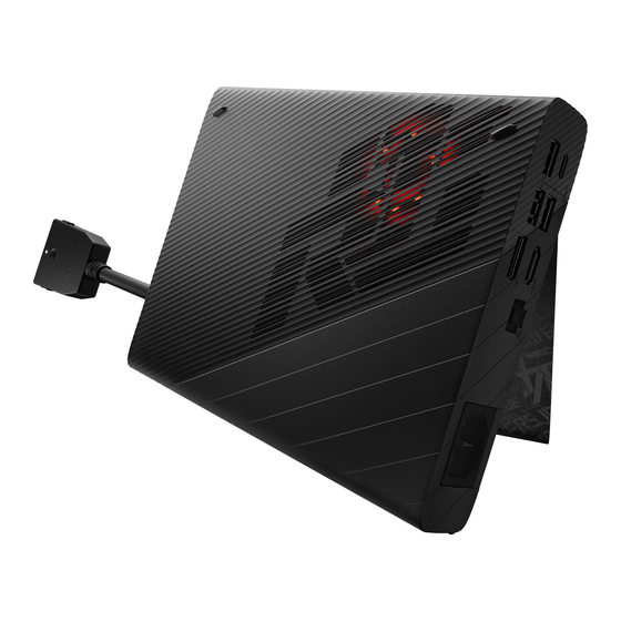
ASUS ROG XG MOBILE Overview Front View Rear View ❶ Kickstand ❶ Air vents Top View Left View ❶ Memory card reader ❷ Air vents ❶ Air vents ❷ Status indicator ❸ Release clips ❹ Unlock switch ❺ Status indicator Right View ❶... -
Page 7: Components Top View
Components Top View ⧫ BOTTOM CASE ⧫ ADAPTER OPEN FRAME ⧫ LED SPONGE (*6PCS) ⧫ TOP CASE ⧫ FIN CONDUCTIVE TAPE ⧫ THERMAL ASSY ⧫ THERMAL FAN ⧫ VGA ADP CABLE ⧫ VGA MAIN BOARD ⧫ THERMAL MYLAR ⧫ ADP GASKET Back... - Page 8 Components Top View ⧫ BOTTOM CASE ⧫ VGA MAIN BOARD ⧫ ADAPTER OPEN FRAME ⧫ THERMAL FAN ⧫ TOP CASE ⧫ THERMAL ASSY Back...
-
Page 9: Repair Overview
Repair Overview This chapter describes disassembly and assembly (Assemble document please look up from the last page), please follow the information provided in this section to perform the complete disassembly procedure. ⧫ Precautions: Before you perform any service or repair on the notebook, please pay special attention to the cautions prevent any damages to the notebook. 1. -
Page 10: Appropriate Tools
Appropriate Tools Please prepare and select the appropriate tools to disassemble/assemble for the ASUS ROG XG MOBILE (GC33) . ⧫ Screwdriver ⧫ Alcohol 95% ⧫ Glove ⧫ Dust-free Cloth Please accord to different screw specification to choose different screwdriver and head. -
Page 11: Top Case
TOP CASE Disassembly Notice Please be sure to pull out adapter. Screws Spec Torque (kgf-cm) Step 1 : Flip up DOOR cover. M2.5*10L(5.1,0.9) (K)+H #1 2.5±0.2 Step 2 : Remove screws*5pcs. M2.5*25L(4.5,0.8) (K) #1 2.5±0.2 Step 3 : Use plastic blade to pry the TOP case. M2.5*10L (K) B-ZN NY 2.5±0.2 Remove... -
Page 12: Adapter Open Frame
ADAPTER OPEN FRAME Screws Spec Torque (kgf-cm) Disassembly Notice Please be sure to pull out adapter. M2.5*5L (K) B-ZN NY #1 2.5±0.2kgf .cm Step 1 : Disconnect the adapter connector (yellow mark). Step 2 : Tear off the mylar and gasket (green mark) on the VGA MAIN BOARD. Step 3 : Remove screws*2pcs. - Page 13 VGA MAIN BOARD Module (includes THERMAL ASSY) Disassembly Notice Please be sure to pull out adapter. Screws Spec Torque (kgf-cm) M2.5*5L (K) B-ZN NY #1 2.5±0.2 Step 1 : Remove screw*1pc. Step 2 : Lift the Adapter cable out of the notch. Step 3 : Lift up and remove the module (includes THERMAL ASSY).
-
Page 14: Vga Adp Cable
VGA ADP CABLE Disassembly Notice Please be sure to pull out adapter. Screws Spec Torque (kgf-cm) M2*3L (K) B-ZN NY #1 1.25±0.2 Step 1 : Disconnect DC-OUT connector (green mark). Step 2 : Remove screws *4pcs. Assembly Notice Disconnect Please ensure to paste FIN CONDUCTIVE TAPE*3pcs on MB module and to assemble as illustrations. -
Page 15: Thermal Fan
THERMAL FAN Disassembly Notice Please be sure to pull out adapter. Screws Spec Torque (kgf-cm) M2*3L (3.5,0.5) (K) #1| 2.5±0.2 Step 1 : Disconnect FAN connector. Step 2 : Remove screws*2pcs and release mylar (green mark). Step 3 : Remove the FAN. Assembly Notice Please use the correct technique to take fans off Disconnect... -
Page 16: Thermal Assy
THERMAL ASSY Assembly Notice Disassembly Notice Please be sure to pull out adapter. Step-1 Screws Spec Torque (kgf-cm) THERMAL MODULE Location:[VRAM/CHOKE/MOS] Material: FCR-AS Grease M2.5*6L (5.0,1.0) (K) #1 2.5±0.2 MB Location:[GPU] Step 1 : Tear off the Tapes *3pcs (red mark). Material: Step 2 : Please follow reverse order to remove and release screws *4pcs. - Page 17 VGA MAIN BOARD Module (include THERMAL ASSY) VGA Main Board Module connector placement and materials on mainboard GC31S IO GASKET DC-OUT GC31S HINGE MYLAR ADP CABLE1 ADP CABLE2 Assembly Notice Assembly Notice DC-IN DO NOT let LAN GASKET contact the signal The LED SPONGE needs to be pressed to stick and nodes or pins in order to avoid short circuits.
Need help?
Do you have a question about the ROG XG MOBILE and is the answer not in the manual?
Questions and answers