Page 1
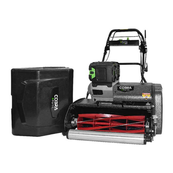
Fortis Cylinder Mower Powered by EGO Power+ 56V Battery MODELS: FORTIS 14E, 17E, 20E, 20FTE, 25FTE, 25E OPERATOR’S MANUAL Cobra Garden Machinery Henton and Chattell Ltd., London Road, Nottingham NG2 3HW UK www.cobragarden.co.uk...
Page 2
WARNING: For your own safety please read this manual before attempting to operate your new unit. Failure to follow instructions can result in serious personal injury. Spend a few moments to familiarise yourself with your mower before each use. Keep this manual in a safe place, so that the information is available at all times.
1.SYMBOLS MARKED ON THE PRODUCT WARNING: For your own safety please read this manual before attempting to operate your new mower. Failure to follow instructions can result in serious personal injury. Spend a few moments to familiarise yourself with your mower before each use. Symbols and Warnings Read the instruction handbook and follow all warning and safety instructions.
WARNING: Keep the safety signs clear and visible on the equipment. Replace the safety signs if they are missing or illegible. 2. GENERAL SAFETY RULES WARNING: When using the cylinder mower, basic safety precautions, including the following, should always be followed to reduce the risk of serious personal injury and/or damage to the unit. Read all these instruction before operating this product and retain these instructions for future reference.
Page 6
14. Keep your feet well away from the blade when starting the mower and in accordance with the instructions. 15. Do not tilt the cylinder mower when starting or switching on the motor and always start on a flat surface free from long grass. 16.
3. PARTS DESCRIPTIONS Notice: the illustrations may vary from your present model (Fig.2) 1. Drive clutch lever 7. Release for handle 13. Key 19. Battery release hole 2. Upper handle 8. EGO Power unit 14. LED screen 20. Tilt protection bracket 3.
4. ASSEMBLY Unpacking: Remove the mower, fixings, tools and other items from the carton. Warning: The mower is heavy. Take care when lifting and handling. Warning: Ensure that cables are not pinched or damaged whilst removing from the package. Warning: Remove the battery from the mower to prevent accidents during assembly Assembly of handlebar: Fig.3 1.
Page 9
Press the power button on the battery (See Fig.5) to display the charge level or its working condition via the 5 LED indicator. The charge levels are as follows: Battery charge 5-LED level / working Remarks indicator condition 80% ≤ Charge 5-LED shining green level ≤...
Page 10
Charging the battery NOTE: The battery is not shipped fully charged. It is recommended to fully charge before use to ensure that maximum run time can be achieved. This lithium-ion battery will not develop a memory and may be charged at any time. In normal conditions a 5Ah battery (BA2800/BA2800T) can be full charged in approximately 100 mins with the standard charger (CH2100E).
Page 11
BATTERY AND CHARGER RECOMMENDATIONS The charger is for indoor use only Recharge only with the charger specified by the manufacturer. A charger that is suitable for one type of battery pack may create risk of fire when used with another battery pack. Use power tools only with specifically designated battery packs.
PREPARING FOR USE Check and Tighten Fixings Before operating the mower inspect all fixings. Check screws, nuts and bolts and tighten as necessary. Fit the Grass Collector Fit catcher by hooking the base of the catcher over the support studs (A) on the body of the mower.
Page 13
Tilt protection bracket The Fortis cylinder mowers incorporates a tilt protection bracket to ensure the safe mower incline angle is not exceeded. Fig.10 Parking Brake The Fortis cylinder mowers feature a parking brake for additional safety. When the mower is stationary for any time always engage the parking brake.
Page 15
Lawnmowing Procedure Preparation Warning: Check the area to be mowed thoroughly to remove debris from the lawn which may be projected from the mower. Stones, twigs, wire, and other debris will damage the cylinder mower. Operators must be familiar with the controls before taking control of the cylinder mower. Bystanders and animals should be a safe distance away from the mowing area.
Page 16
How to Stop the cylinder mower Fig. 13 Warning: The blade and drive will not stop immediately. In the case of an emergency ‘STOP’ release both the cutting cylinder and drive control levers, the double motion hook (safety lever) will return back to the starting position. The motor of the power unit will continue to run but the cutting cylinder and power drive will stop.
Page 17
1. Ensure the mower is stopped prior to removing or refitting the grass collector. 2. The grass collector is fitted by holding the top of the box and hooking the bottom section to the locating pegs (A), the catcher then sits on the rubber stops (B) either side of the chassis. 3.
Page 18
5. Re-tighten bolts. Fig. 17 & Fig. 6. Test the cutting action with paper as previously described. Should the paper not cut satisfactorily, the cylinder may need to be sharpened. Contact your local Cobra dealer. Fig. 17 Fig. 18 Fig. 19 Fig.
Page 19
4. Re-tighten the lock nut. Fig. 24. 5. Refit the side cover and secure with the two screws. Fig. Fig. 23 Fig. 24 Fig. 25 Drive Control Adjustment Warning: Switch off the power unit before making any adjustments of maintenance. The drive control lever mechanism is adjustable to apply more or less tension on the drive belt.
Page 20
Handle Position Adjustment Fig. 27 Fig. 28 Fig. 29 The height of the handles may be adjusted to suit the operator. At the lower section of the handle, the securing bolts should be loosened to adjust the angle of the handles. The side cover should be removed to access the two bolts on this side. Once the required height is set, secure the bolts on each side.
The cylinder mower must be serviced regularly. For normal homeowner use, the cylinder mower should be serviced by a Cobra service dealer annually, however where the cylinder mower is used more frequently ensure the cylinder mower is serviced more regularly.
Page 22
Removing and Fitting the Fortis Cartridge Fig. 31 Fig. 32 Fig. 33 Fig. 34 Fig. 35 Fig. 36 Removing the cartridge 1. Remove the side cover, unscrewing the 2 bolts highlighted in the red circle. Fig.31 2. On the other side of the mower, remove the bolts securing the cartridge which is highlighted in Fig.32.
Check and adjust the gap. Check and ‘on-cut’ across the whole blade. The sharpen the cylinder if necessary. consistent. Some blade system is damaged. areas are not cut Damaged – see a Cobra dealer correctly. Power unit starting Battery not located correctly Refit the battery issues.
Any damage that occurs from the use of non-genuine Cobra parts will not be covered. We reserve the right to reject any claim where the purchase cannot be verified or when it is clear that the product was not maintained properly.
12. EC DECLARATION OF CONFORMITY EC Declaration of Conformity We herewith declare, Cobra Garden Machinery Henton & Chattell Ltd, London Road, Nottingham NG2 3HW UK That the following machine complies with the appropriate basic safety and health requirements of the EC Directive based on its design and type, as brought into circulation by us.
Need help?
Do you have a question about the FORTIS 14E and is the answer not in the manual?
Questions and answers