Advertisement
Advertisement
Table of Contents

Summary of Contents for Tesla 1529455 Series
- Page 1 Gen 3 Wall Connector Manual...
-
Page 2: Product Specifications
PRODUCT SPECIFICATIONS This manual applies to Wall Connectors identified by part number 1529455-**-*. Voltage and Wiring 1-phase 230 V L-N 3- phase 230 V L-L 3- phase 400 V L-L Current Output Range Maximum 32 A (adjustable by installer) Terminal Blocks Stranded: 4-25 mm , copper only Solid: 1.5-20 , copper only... - Page 3 WALL CONNECTOR LABEL Each Wall Connector has a label on the exterior side with information that is unique to the product, including: • TPN: Tesla Part Number • TSN: Tesla Serial Number • Input: Max input power • Output: Max output power •...
-
Page 4: Power Supply Options
POWER SUPPLY OPTIONS For basic operation, Wall Connector requires an electrical connection to Line 1, Neutral, and Protective Earth (PE) terminals. Connection to Line 2 and Line 3 terminals is supported for some grid types. CAUTION: Wall Connector supports 230 V L-N (+/- 10%). Mis-wiring the neutral terminal with >264V to PE can damage Wall connector Wall Connector can operate on a three-phase power supply or a single-phase power supply. - Page 5 POWER SUPPLY OPTIONS Table 2. 2nd Most Common Installation Option Wiring Configuration Option for Three Wires: Line 1, Neutral, PE Grid type options: • 230 V Line to Neutral • 230 V Line to Line NOTE: For 230V Line to Line connections, without a Neutral, connect one Line from the grid to the Neutral terminal of the wirebox CAUTION: Double check N connection is 230 V...
- Page 6 POWER SUPPLY OPTIONS Table 3. Least Common, but Supported Installation Option Wiring Configuration Option for Four Wires: Line 1, Line 2, Neutral, PE Grid type options: • Delta 230 V Line to Line • Open wye with 230 V Line to Neutral •...
- Page 7 USING WALL CONNECTOR 1. Open the vehicle charge port by pressing the button on the charge handle, pressing on the charge port door, using the mobile app, using the vehicle touchscreen, or by pressing and holding the trunk button on the keyfob. 2.
-
Page 8: Local Network
Connectivity Wall Connector is equipped with Wi-Fi to communicate with local site routers, vehicles, mobile devices, other Wall Connectors, and other Tesla products. Hosted Access Point Wall Connector hosts a WPA2 password-secured, 2.4 GHz, 802.11 Wi-Fi access point network to facilitate commissioning and connecting to other devices. -
Page 9: Residual Current Device (Rcd)
FEATURES NOTE: Networks that are not password protected are not supported. The Wall Connector will not display non-password protected networks in the options list.Open networks without a password are not supported and will not be recognized by the Wall Connector. NOTE: WPA enterprise will be supported in a future firmware update. -
Page 10: Power Outages
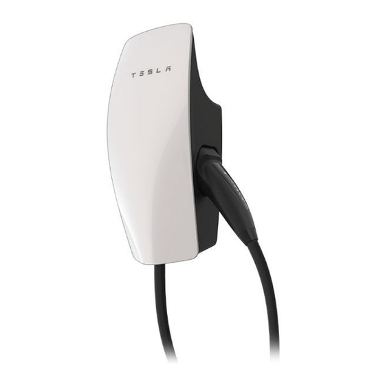
FEATURES Power Outages If there is a power outage while Wall Connector is charging a vehicle, charging will automatically resume within 1 to 3 minutes after power restoration. The Wall Connector will display a solid blue light on the faceplate to indicate that it is communicating with the vehicle and waiting to resume charging. - Page 11 WALL CONNECTOR EXTERNAL COMPONENTS "Wall Connector" refers to the product as a whole. 1. Faceplate 2. Light bar (vertical) 3. Main unit 4. Charge handle button 5. Charge handle Gen 3 Wall Connector Manual...
- Page 12 WALL CONNECTOR INTERNAL COMPONENTS 1. Contact blades 2. Temperature sensor 3. Conductor terminals 4. Zip tie anchor 5. Sliding contacts 6. Wirebox drainage opening (enables protection) 7. Neutral 8. Line 1 9. Line 2 10. Line 3 11. Earth Gen 3 Wall Connector Manual...
- Page 13 IN THE BOX Hex Bit (4 mm) Wirebox Mounting Template Main Unit Wirebox Wirebox-to-Wall Fastener (x2) 4.0 x 50 mm (PZ2) Wall Connector-to- Wirebox Fastener (x4) Zip tie (x1) (#8 x 2 in) Quickstart Guide (contains sticker with SSID network name and unique password) NOTE: The hex bit, zip tie, and fasteners are located in a plastic bag inside the wirebox, which comes attached to the main unit of the Wall Connector.


Need help?
Do you have a question about the 1529455 Series and is the answer not in the manual?
Questions and answers
Forgotten password
The Wall Connector with part number 1529455 Series has a unique SSID and WPA2 password printed on a label at the rear of the main unit and on the front cover of the Quickstart Guide included in the box. If the password is forgotten, check these locations to retrieve it. There is no mention of a reset procedure for a forgotten password in the provided information.
This answer is automatically generated