Lux Power Technology SNA-EU 12K User Manual
Off-grid inverter
Hide thumbs
Also See for SNA-EU 12K:
- User manual (56 pages) ,
- User manual (30 pages) ,
- User manual (20 pages)
Table of Contents
Advertisement
Quick Links
Advertisement
Table of Contents

Related Manuals for Lux Power Technology SNA-EU 12K


Summary of Contents for Lux Power Technology SNA-EU 12K
- Page 1 Off-grid Inverter User Manual SNA-EU 12K Version: UM-SNA04001...
- Page 2 User Manual Copyright© 2024 Lux Power Technology Co., Ltd. All Rights Reserved. This manual, protected by the copyright and intellectual property rights of Lux Power Technology, may not be modified, copied, or reproduced without prior written permission. Brands and trademarks mentioned belong to their respective owners.
-
Page 3: Table Of Contents
User Manual Table Of Contents Information on this Manual Validity Scope Target Group Safety Instructions 1. Brief Introduction 1.1 Features of the inverter 1.2 Interface of the inverter 1.3 Packing list 2. Installation 2.1 Preparation 2.2 Mounting the Unit 2.3 Battery Connection 2.3.1 Battery Power Cable Connection 2.3.2 Lithium Battery Connection 2.4 CT... - Page 4 User Manual 4.2 LCD Display 4.3 Inverter Status Display 4.4 LCD Settings 5. About LCD Settings check the operation 6. Monitor System for ECO Hybrid inverter 7. Specifications 8. Trouble Shooting & Error List Revision History Version Date Description UM-SNA04001 2024.07.11 First official release.
-
Page 5: Information On This Manual
User Manual Information on this Manual Validity This manual is valid for the following devices: SNA-EU 12000 Scope This manual provides the installation, operation and troubleshooting of this unit, please read this manual carefully before installations and operations. Target Group For qualified persons and end users. -
Page 6: Brief Introduction
User Manual 1. Brief Introduction 1.1 Features of the inverter LuxPower APP Internet Wifi/4G User name Pass word Remember username Auto login LOGIN Forget password? REGISTER DONGLE CONNECT LOCAL CONNECT PRODUCT WARRANTY DOWNLOAD FIRMWARE Version 3.2.3 - Privacy Policy Luxpower Server Solar Panel Home Utility Grid... -
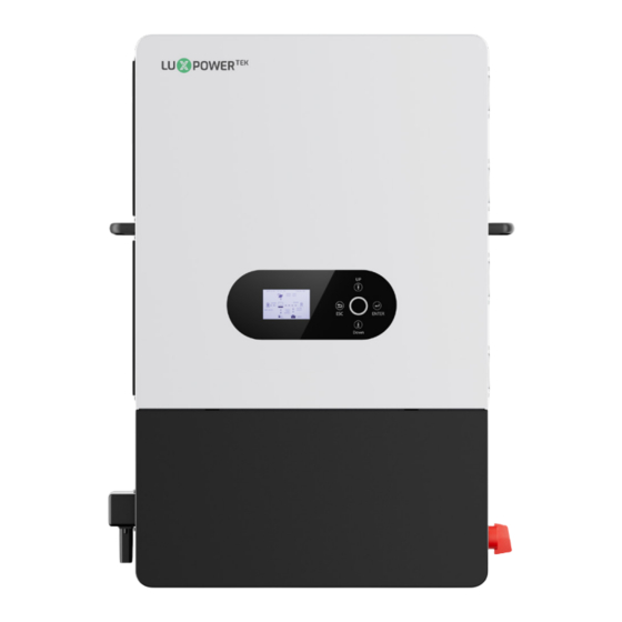
Page 7: Interface Of The Inverter
User Manual 1.2 Interface of the inverter Status indicator (Normal/Warning/Fault) LCD display Function buttons BAT.NTC M3.COOM PV Terminal PV Switch BAT.COM Parallel WiFi/GPRS GEN Terminal BAT+ Breaker GRID Terminal Power on/off switch EPS on/off switch LOAD Terminal SMART LOAD Terminal Parallel communication ports Battery CAN/RS485 Dry contacts... -
Page 8: Packing List
User Manual 1.3 Packing List Before installation, please inspect the unit. Be sure that nothing inside the package is damaged. You should have received the following items in the package: Expansion Screw and Tube X6 User Manual X1 Offgrid inverter X1 Cross Head Screw M8(6PCS) Mounting... - Page 9 User Manual Temperature<60℃ Height<2m Humidity<85%...
-
Page 10: Installation
User Manual 2. Installation 2.1 Preparation The system connection is as below: 600V, 2*4AWG Generator 600V, 2*4AWG Grid Grid 600V, 2*4AWG Load LOAD1 600V, 2*4AWG Smart Load LOAD2 P V1 P V2 600V, 4*8AWG QF 1 In≥100A QF 2 In≥63A QF 1 is Double inter lock switch or Dual Power Switch In≥100A Please prepare the breakers and cables in advanced before installation. - Page 11 User Manual 2. AC connection: Please install a separate AC breaker between inverter and AC input power source, inverter and AC output load. This will ensure the inverter can be securely disconnected during maintenance and fully protected from over current of AC input. Recommended AC input/AC output/GEN cable size for each inverter.
-
Page 12: Mounting The Unit
User Manual 2.2 Mounting the Unit NOTICE Consider the following points before selecting where to install: Mount on a solid surface. Do not mount the inverter on flammable construction materials. For proper air circulation to dissipate heat, allow a clearance of approx. 20cm to the side and approx. -
Page 13: Battery Connection
User Manual 2.3 Battery Connection 2.3.1 Battery Power Cable Connection Note: for lead acid battery, the recommended charge current is 0.1-0.25C (C to battery capacity). 1. Please follow below steps to implement battery connection: 2. Assemble battery ring terminal based on recommended battery cable and terminal size. 3. - Page 14 User Manual 2.4 CT To measure the power imported from and exported to the grid, a pair of Cts must be installed at the service entry point in or near the main service panel. "External Grid CT" function is off by default, and if you need inverter to export power to compensate the grid loads, you can set "External Grid CT"...
- Page 15 User Manual Please refer to the connection diagram for the correct positions of Grid CT and clamp the CT on the wires at the service entry point in the main service panel. The arrow on the CT is pointing to the inverter.(*** Incorrectly install CT will cause the display to show incorrect information and features of the inverter will not function correctly) If the CT is in a wrong direction, there is an option you can change the direction of the CT on your inverter call: CT Direction Reversed in Advanced Tab.
-
Page 16: Ac Input/Output Connection
User Manual 2.5 AC Input/Output Connection CAUTION - There are two terminal blocks with “IN” and “OUT” markings. Please do NOT mis-connect input and output connectors. - Be sure to connect AC wires with correct polarity. If L and N wires are connected reversely, it may cause utility short-circuited when these inverters are worked in parallel operation. -
Page 17: Pv Connection
User Manual 2.6 PV Connection Please follow below steps to implement PV module connection: 1. Remove insulation sleeve 10 mm for positive and negative conductors. 2. Check correct polarity of connection cable from PV modules and PV input connectors. 3. Connect positive pole (+) of connection cable to positive pole (+) of PV input connector. Connect negative pole (-) of connection cable to negative pole (-) of PV input connector. -
Page 18: Dry Contact Signal Control
User Manual All lux units can work with generator: Users can connect the generator output to the SNA series inverters via the GEN input terminal. The generator automatically starts when the battery voltage falls below the cut-off value or when there is a charge request from the BMS. -
Page 19: Parallel Function
User Manual 2.9 Parallel Function SNA series inverter support up to 16 units to composed single phase parallel system or three phase parallel system, for parallel system setup. Step 1. Cable connection: the system connection is as below:... - Page 20 User Manual...
- Page 21 User Manual Step 2. Please put the CAN communication PIN to on status for the first and the end inverter. No.1 No.2 No.n-1 No.n Parallel Parallel Parallel Parallel Parallel line1 Parallel line2 Parallel line (n-1 to n) Parallel line (n to 1) The max parallel quantity is 10, so 2≤n≤10 Step 3.
-
Page 22: Power And Eps On/Off
User Manual 2.10 Power and EPS ON/OFF 1. Power Switch: Control power supply for the unit 2. LOAD Output Switch: Use to control the AC output After connection, please turn on both switch. Users can turn off the LOAD output switch to turn off power supply in some emergency case. - Page 23 User Manual PV+Battery power the load PV+BAT Grid off together. 1.When the LOAD key off, the inverter charge the battery only. PV Charge 2.When the battery is power off, the PV can wake up the battery automatically. PV charge the battery and PV Charge+Grid off power the load.
-
Page 24: Working Modes Related Setting Description
User Manual... -
Page 25: Working As A Hybrid Inverter. Related Settings
User Manual 3.3 Working as a hybrid inverter. Related settings 3.3.1 The SNA series can function as a traditional off-grid inverter or a hybrid inverter. When PV&AC take load jointly is disabled, it operates as a traditional off-grid inverter. Otherwise, it works as a hybrid inverter. -
Page 26: Lcd Display And Settings
User Manual According to Time: During the setting time, system will use AC to charge the battery until battery full and battery will not discharge during the setting time. According to Battery Voltage: During the setting voltage, system will use AC to charge the battery if battery voltage is lower than AC Charge Start Battery Voltage and will stop when Voltage is higher than AC Charge End Battery Voltage. - Page 27 User Manual Description Remarks Generally Information Display the currently time/date by default. Display Area This area shows the data of Two-chnnel PV Solar inverter output power voltage and power. This area shows the battery type, (lithium battery Battery information and data or lead Acid battery), display the voltage, SOC , input and output power.
- Page 28 User Manual 4.3 Inverter Status Display When the SNA-EU 12000 inverteris running normally, the text information corresponding to the current working Warning Status, warning 04 status is displayed in the red box, such as PVGridOn or PVCharge. Fault status, fault 02 Flash status: download percent is 58% If the system displays the icon in the red When the icon in the red box is...
- Page 29 User Manual 4.4 LCD Settings Button Operations Button Function Exit ENTER Confirm, Enter menu Previous leval, Increase DOWN Next leval, Decrease Note: Long-pressing the UP and DOWN keys will continuously input the correspongding key signals. General Operations Through button control, press ENTER on the home screen to access the menu options Enter Using the UP and DOWN buttons, select the desired function, then press ENTER to enter.
- Page 30 User Manual Index Description Data Solar The figure shows the voltage and power of Pv1, the voltage and power of PV2, the power generation of PV1 in one day and the total power generation of PV1, the power generation of PV2 in one day and the total power generation of Pv2.
- Page 31 User Manual Grid (1) The first page contains the following information: grid voltage, grid frequency, generator voltage,generator frequency, power input from the grid to the inverter, power output from the inverter to the grid, inverter power, rectified power, load power. Grid (2) The second page contains the following information: The power of the inverter exported to the grid during the day.
- Page 32 User Manual Parallel This page contains information about the role of the machine in the parallel state (host or slave). Parallel type (single phase or three phase). Parallel phase ® or S or T). Number of parallel machines. Parallel address. Other This page contains text information about the current status of the inverter.
- Page 33 User Manual Index Description Notice Fault Status Information on this page: When the inverter fails, this page displays the corresponding fault code. If there is NO Fault, no fault is displayed. Alarm Status Information contained in this page: When the inverter alarm appears, this page will display the corresponding alarm code.
- Page 34 User Manual Index Description Setting Battery brand Battery brand Standard HinaESS Aobo SHINWA Beta Pylon Dyness WeCo Revov Enopte Stealth Murata Beebeej M SUN TeLongM ei BITek Naxin GSL1 M erit OKSolar Soltaro The first page contains the following information: inverter status information (rated or standby).
- Page 35 User Manual Application (2) The second page contains information: AC priority charging time, you can set three time periods. Application (3) The third page contains the following information: Mixed mode Settings. PV and AC are loaded together. empowerExport to the grid. Percentage of electricity output to the grid.Enable the CT function on the inverter power grid side.
- Page 36 User Manual Charge (1) The first page contains information: charging current Settings. CV voltage setting of lead-acid battery. Lead-acid battery floating charge voltage setting. Charge (Numerical setting operation) This page contains: Setting values. After pressing Down, exit move to +1, +1 to -1, -1 to +0.1, +0.1 to -0.1, and -0.1 to Enter. Press UP to roll back.
- Page 37 User Manual Charge (according to the time) The second page contains information: The AC is charged according to the time, and three time periods are provided. Charge (according to the battery voltage) The second page contains information: The AC is charged according to the battery voltage. The starting charge voltage and cut-off charge voltage can be set.
- Page 38 User Manual Charge (according to the battery voltage and time) The second page contains information: The AC is charged according to the battery voltage and time. Meet one of the three time periods and the battery voltage between the starting charge voltage and the cut-off charge voltage.
- Page 39 User Manual DisCharge (1) The first page contains information: battery discharge can be based on voltage or SOC. Discharge current can be set. Battery alarm voltage can be set. Off-grid discharge cutoff voltage can be set. Grid-connected discharge cutoff voltage can be set. The alarm voltage is larger than the off-grid cut-off voltage.
- Page 40 User Manual Other Include information: CT power compensation setting. Set the maximum speed of five fans. Set five fan control slope curves. Basic Contains information: SN Indicates the serial number of the inverter. FW Indicates the firmware version of the inverter (cEaa indicates the US version, cFaa indicates the European version).
- Page 41 User Manual 6. Monitor System for ECO Hybrid inverter Users can use wifi dongle/WLAN dongle/4G dongle (Avaiblable from 2021 March for some countries) to monitor the energy storage system, The monitor website is: server.luxpowertek.com. The APP is also available in the google play and apple APP store (Scan two code bar to download the APP).
- Page 42 User Manual 7. Specifications Table 1 MPPT Mode Specifications INVERTER MODEL SNA-EU 12000 Max. PV Array Power (W) 24000W (12000/12000) Rated PV Input Voltage (V) Number of Independent MPPT Inputs 100~480 PV Input Voltage Range (V) 120~385 MPPT Voltage Range (V) Start-up Voltage (V) Max.
- Page 43 User Manual load < 20% 44.0Vdc (Settable) Low DC Warning 20% ≤ load < 50% Warning Voltage@load < 20% -1.2V Voltage (Lead Acid) load ≥ 50% Warning Voltage@load < 20% -3.6V Low DC Warning Return Voltage(Lead Acid) Low DC Warning Voltage@Different load+2V load <...
- Page 44 User Manual Table 3 Line Mode Specifications INVERTER MODEL SNA-EU 12000 Input Voltage Wavefor Sinusoidal (utility or generator) Nominal Input Voltage (V) 230Vac Low Loss Voltage 170Vac±7V (UPS); 90Vac±7V (Appliances) Low Loss Return Voltage 180Vac±7V (UPS); 100Vac±7V (Appliances) High Loss Voltage 280Vac±7V High Loss Return Voltage 270Vac±7V...
- Page 45 User Manual Table 4 Generator Mode Specifications INVERTER MODEL SNA-EU 12000 Rated GEN Voltage (V) Rated GEN Frequency (Hz) 50/60 Rated GEN Input Current (A) Rated GEN Input Power (W) 15000 Rated GEN Current of Bypass Relays (A) Table 5 Protection/General Specifications INVERTER MODEL SNA-EU 12000 Over Current/Voltage Protection...
- Page 46 User Manual 8. Trouble Shooting & Error List The failures mainly divided into 5 categories, for each category, the behavior is different: Code Description Trouble shooting Restart inverter, if the error still exist, contact us E000 Internal communication fault1 (DSP&M3) Restart inverter, if the error still exist, contact us E001 Model fault...
- Page 47 User Manual Code Description Trouble shooting Check if you have choose the right battery brand Communication failure with battery W000 and communication cable is right, if the warning still exist, contact us Restart inverter, if the error persists, contact AFCI Com failure W001 your supplier.
- Page 48 Lux Power Technology Co., Ltd Headquarter: +86 755 8520 9056 www.luxpowertek.com Contact us: info@luxpowerttek.com 092.20044AA...
Need help?
Do you have a question about the SNA-EU 12K and is the answer not in the manual?
Questions and answers