Advertisement
Quick Links
Installation and Operation Instructions
Please read all instructional literature carefully and thoroughly before starting.
GENERAL
MISUSE OF THIS PRODUCT MAY CAUSE EXPLOSION
AND PERSONAL INJURY. THESE INSTRUCTIONS MUST
BE THOROUGHLY READ AND UNDERSTOOD BEFORE
DEVICE IS INSTALLED.
PRIOR TO INSTALLATION, CHECK THE WETTED PARTS
MATERIAL FOR COMPATIBILITY TO THE PROCESS MEDIA.
Cert number
20190829-E40857
Applicable Area
North America
Class I, Div. 2, Groups A, B, C and D;
Markings
Class II, Div. 2, Group F and G, enclosure
Type 4X
ANSI/ISA 12.12.01, UL 508; C22.2 No. 14,
Applicable Standards
C22.2 No. 213
Cert number
DEMKO 11 ATEX 1105261X
Applicable Area
Europe (EU)
Markings
II 1 G Ex ia IIC T6 Ga
Applicable Standards
EN IEC 60079-0; EN 60079-11
Cert number
IECEx UL 14.0075X
Applicable Area
International
Ex ia IIC T6 Ga
Markings
-50°C ≤ Tamb ≤ +60°C
Applicable Standards
IEC 60079-0; IEC 60079-11
117 SERIES FOR USE IN CLASS I, DIV. 2, GROUPS A, B,
C AND D; CLASS II, DIV. 2, GROUPS F AND G; CLASS III;
OR NON-HAZARDOUS LOCATIONS ONLY. ENCLOSURE
TYPE 4X, IP66. AMBIENT TEMPERATURE RANGE -50°C
(-58°F) TO 71°C (160°F).
ATEX AND IEC SPECIFIC CONDITIONS OF USE:
ENCLOSURE CONTAINS ALUMINUM. CARE MUST BE
TAKEN TO AVOID IGNITION HAZARD DUE TO IMPACT
OR FRICTION.
THIS PRODUCT DOES NOT HAVE ANY FIELD REPLACEABLE
PARTS. ANY SUBSTITUTION OF COMPONENTS SHALL
INVALIDATE AGENCY CERTIFICATION(S), AND IMPAIR
SUITABILITY FOR CLASS I, DIV. 2 LOCATION.
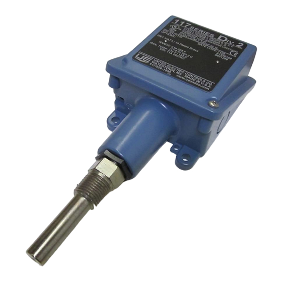
The 117 series pressure and diff erential pressure
switch utilizes a bellows or diaphragm sensor to
detect a pressure change.
117 Series
Type H117 (Pressure Switch)
Type H117K (Diff erential Pressure Switch)
Refer to the final page for the Warranty.
The response, at a pre-determined set point,
actuates a SPDT or DPDT snap-acting switch,
converting the pressure signal into an electrical
signal. Control set point may be varied by turning
the internal adjustment hex (see Adjustment-Part II).
PROOF PRESSURE* LIMITS STATED IN THE
LITERATURE AND ON NAMEPLATES MUST NEVER
BE EXCEEDED, EVEN BY SURGES IN THE SYSTEM.
OCCASIONAL OPERATION OF UNIT UP TO PROOF
PRESSURE IS ACCEPTABLE (E.G. START-UP, TESTING).
EXCESSIVE CYCLING AT MAXIMUM PRESSURE
LIMITS COULD REDUCE SENSOR LIFE. CONTINUOUS
OPERATION SHOULD NOT EXCEED THE DESIGNATED
OVER RANGE** OR WORKING PRESSURE RANGE ***.
*
Proof Pressure - the maximum pressure to which a pressure sensor
may be occasionally subjected, which causes no permanent damage
(e.g., start-up, testing). The unit may require re-gapping.
**
Over Range Pressure - the maximum pressure to which a pressure
sensor may be continuously subjected without causing damage and
maintaining set point repeatability.
***
Working Pressure Range - the pressure range in which two oppos-
ing sensors can be safely operated and still maintain set point provided
the diff erence in pressure between the low and high sides does not
exceed the designated adjustable range.
DEVICE MUST NOT BE ALTERED OR MODIFIED AFTER
SHIPMENT. CONSULT UE IF DEVICE MODIFICATION IS
NECESSARY.
Please refer to product datasheet at www.ueonline.com
for product specifi cations. Date code format on
nameplate is "YYWW" for year and week.
Part I - Installation
•
Adjustable Wrench
•
Screwdriver
•
Hammer (for alternate wire knockouts)
Mounting
INSTALL DEVICE WHERE SHOCK, VIBRATION AND
TEMPERATURE FLUCTUATIONS ARE MINIMAL. DO NOT
INSTALL DEVICE IN AMBIENT TEMPERATURES THAT
EXCEED PUBLISHED LIMITS ON THE NAMEPLATE.
1
IMP117 11
Advertisement

Subscribe to Our Youtube Channel
Related Manuals for United Electric Controls 117 Series


Summary of Contents for United Electric Controls 117 Series
- Page 1 Please refer to product datasheet at www.ueonline.com for product specifi cations. Date code format on 117 SERIES FOR USE IN CLASS I, DIV. 2, GROUPS A, B, nameplate is “YYWW” for year and week. C AND D; CLASS II, DIV. 2, GROUPS F AND G; CLASS III;...
- Page 2 A grounding screw and clamp (cast in symbol) is DEVICE CAN BE MOUNTED IN ANY ORIENTATION BUT VERTICAL MOUNTING IS RECOMMENDED TO PREVENT provided which meets a 35 lb. pull test. Keep the MOISTURE FROM ENTERING THE ENCLOSURE. wire as short as possible to prevent interference with the plunger.
-
Page 3: Recommended Practices
Recommended Practices GAPPING IS FACTORY-SET AND CRITICAL TO THE FUNCTION OF THE SWITCH. THIS PROCEDURE SHOULD ONLY BE PERFORMED IF THE PLUNGER HAS ACCIDENTALLY BEEN ADJUSTED. • A redundant device is necessary for applications where damage to the primary device could ❶... - Page 4 Dimension A Dimension A Models Inches NPT (Inches) Models Inches NPT (Inches) Pressure Differential Pressure 171-174 540-543 8.47 215.1 7.63 193.8 544-548 8.53 216.7 183-186, 483-486 7.56 192.0 188-189, 488-489, 190-194, 490-494 6.63 168.4 6.56 166.6 358-376 7.00 177.8 520-525 8.44 214.4 530-535...
- Page 5 Le 117 Series est adapté à une utilisation dans 117 SERIES FOR USE IN CLASS I, DIV. 2, GROUPS A, B, C AND les lieux de Classe I, Division 2, de Groupes A, B, C et D ; Classe D;...
-
Page 6: Limited Warranty
LIMITED WARRANTY LIMITATION OF SELLER’S LIABILITY Seller warrants that the device hereby purchased is, upon Seller’s liability to Buyer for any loss or claim, including delivery, free from defects in material and workmanship and liability incurred in connection with (i) breach of any warranty that any such device which is found to be defective in such whatsoever, expressed or implied, (ii) a breach of contract, (iii) workmanship or material will be repaired or replaced by Seller...
Need help?
Do you have a question about the 117 Series and is the answer not in the manual?
Questions and answers