Table of Contents
Advertisement
Quick Links
Please read all instructional literature carefully and thoroughly before starting. Refer to the final page for the listing of Recommended
Practices, Liabilities and Warranties.
gEnERAL
befOre iNSTALLiNg, cHecK THe SeNSOr MODeL SeLecTeD
fOr cOMpATibiLiTy TO THe prOceSS MeDiA iN cONTAcT WiTH
THe SeNSOr AND WeTTeD pArTS.
The H100 and H100K differential pressure switches are activated when
a bellows, diaphragm or piston sensor responds to a pressure change.
This response, at a pre-determined set point, actuates a single snap-
acting switch, converting the pressure signal into an electrical signal.
control set point may be varied by turning the internal adjustment hex.
(See Adjustment -pArT ii).
prOOf preSSure* LiMiTS STATeD iN THe LiTerATure AND ON
NAMepLATeS MuST NeVer be exceeDeD, eVeN by SurgeS
iN THe SySTeM. OccASiONAL OperATiON Of uNiT up TO
prOOf preSSure iS AccepTAbLe (e.g., STArT-up, TeSTiNg).
cONTiNuOuS OperATiON SHOuLD NOT exceeD THe DeSigNATeD OVer
rANge preSSure.
*Proof Pressure
The maximum pressure to which a pressure sensor may be occasionally
subjected, which causes no permanent damage (e.g., start-up, testing).
The unit may require re-gapping.
Part I - Installation
MounTIng
iNSTALL uNiT WHere SHOcK, VibrATiON AND TeMperATure
fLucTuATiONS Are MiNiMAL. OrieNT uNiT SO THAT MOiS-
Ture iS preVeNTeD frOM eNTeriNg THe eNcLOSure. if
uNiT iS beiNg iNSTALLeD WHere HeAVy cONDeNSATiON iS expecTeD,
VerTicAL MOuNTiNg (preSSure cONNecTiON DOWN) iS requireD. DO
NOT MOuNT iN AMbieNT TeMperATureS exceeDiNg pubLiSHeD LiMiTS.
c o n t r o l s m a y b e m o u n t e d a n d o p e r a t e d i n a n y
position. They may be surface mounted via the two mounting ears on
either side of the enclosure, or directly to a rigid pipe by using the pres-
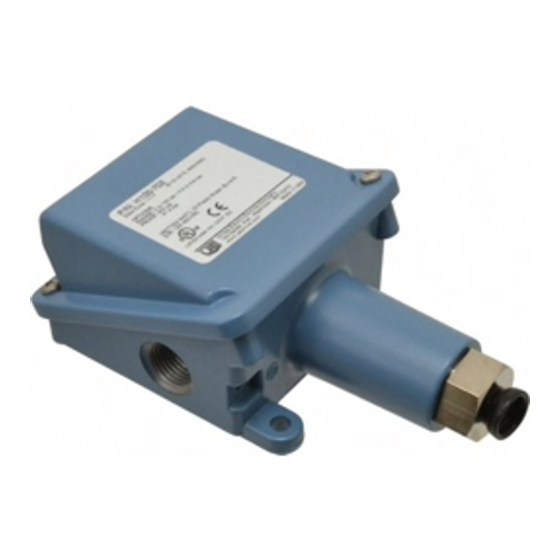
100 Series
Type H100
(Pressure Switch)
Type H100K
(Differential Pressure)
Tools needed
Adjustable Wrench
Screwdriver
Hammer (for alternate wire knockouts)
U N I T E D E L E C T R I C
C O N T R O L S
Installation and Maintenance
Instructions
sure connection. Low pressure and differential pressure units, models
520-535, 540-543, 544-548, are also available with an optional
surface mounting bracket. Should the control be installed where con-
densation is expected, vertical mounting is recommended as a means of
keeping water away from switch terminals.
Never use the enclosure for leverage to hand tighten the pressure con-
nection. Always use a wrench to tighten the pressure connection to the
pipe.To prevent damaging the pressure sensor, use a back-up wrench
to hold the hex nut in place when surface mounting.
On models supplied with an external manual reset button, be sure to
leave sufficient finger space over the reset button for the operator to
reset the control. See Mounting Diagram.
WIRIng
DiScONNecT ALL SuppLy circuiTS befOre WiriNg.
eLecTricAL rATiNgS STATeD iN LiTerATure AND ON
NAMepLATeS SHOuLD NeVer be exceeDeD. OVerLOAD
ON A SWiTcH cAN cAuSe fAiLure ON THe firST cycLe.
Wire uNiTS AccOrDiNg TO NATiONAL AND LOcAL eLecTricAL
cODeS. MAxiMuM recOMMeNDeD Wire Size iS 14 AWg.
remove the two screws retaining the cover and cover gasket. A 1/2" NpT
conduit connection is provided on the left hand side of the enclosure.
Two cast-in knockouts for the 1/2" conduit are located on the side and
back of the enclosure. These can easily be knocked out by placing
the blade of a screwdriver in the groove and tapping sharply with a
hammer. The three switch ter minals are clear ly labeled
"common", "nor mally open" and "nor mally closed". for
optional switches supplied with leadwires, the following color
coding applies:
Manual
Reset
(Option 1530)
SPDT
common
Violet
Normally Open
blue
Normally closed black
IMP100-07
DPDT
(Option 1010)
SWT1
SWT2
Violet
yellow
blue
Orange
black
red
Advertisement
Table of Contents

Subscribe to Our Youtube Channel
Related Manuals for United Electric Controls 100 Series


Summary of Contents for United Electric Controls 100 Series
- Page 1 IMP100-07 100 Series Type H100 (Pressure Switch) U N I T E D E L E C T R I C C O N T R O L S Type H100K Installation and Maintenance (Differential Pressure) Instructions Please read all instructional literature carefully and thoroughly before starting. Refer to the final page for the listing of Recommended Practices, Liabilities and Warranties.
- Page 2 A grounding screw and clamp (cast in symbol) is provided which meets Models Flats Approx. gap a 35 lb. pull test. Keep the wire as short as possible to prevent inter- 171-174 2-2 1/2 .0085 to .0105” face with the plunger and the optional adjustable differential switch wheel, if applicable.
- Page 3 Dimensions Dimension A Model Inches 171-174 7.50 190,5 1/2” 183-186 7.56 192,0 1/2” 188,189 6.62 168,1 1/2” 190-194 6.63 168,4 1/2” 218-274 6.56 166,6 1/4” 358-376 7.03 178,6 1/4” 483-486 7.56 192,0 1/2” 488,489 6.62 168,1 1/2” 490-494 6.63 168,4 1/2”...
- Page 4 Dimensions RECOMMENDED PRACTICES AND WARNINGS United Electric Controls Company recommends careful consideration of the fol- lowing factors when specifying and installing UE pressure and temperature units. Before installing a unit, the Installation and Maintenance instructions provided with unit must be read and understood.
Need help?
Do you have a question about the 100 Series and is the answer not in the manual?
Questions and answers