Table of Contents
Advertisement
Quick Links
Advertisement
Table of Contents

Related Manuals for Senergy 12KHB-D3


Summary of Contents for Senergy 12KHB-D3
- Page 1 USER MANUAL Three-phase ESS Inverter Version: EN-UM-1.2...
- Page 3 HISTORY VERSION ISSUED COMMENTS 08-May.-24 First release 23-May.-24 Update the preface; update CT ratio; update Battery Connection table; update 4.6.3 CT connection; update DI/DO connection; add startup note; update 7.1 Indicator States table; update 8.2 Inverter troubleshooting. 24-JUN.-24 Update packing list; update parallel connection scheme; update silkscreen of communication ports;...
-
Page 4: About This Manual
(Specific product please in kind prevail.) Target Group Three phase ESS inverters must be installed by professional electrical engineers who have obtained relevant qualifications. Scope This manual is applicable to the following inverters: 12KHB-D3 15KHB-D3 20KHB-D3 25KHB-T3 30KHB-T3 Statement All information here takes model 30KHB-T3 as reference and guidance only. -
Page 5: Table Of Contents
CONTENTS Preface About This Manual Target Group Scope Conventions 1. Safety 1.1 Symbols Used 1.2 Safety Precaution 2. Product Introduction 2.1 Overview 2.2 Product Appearance 2.3 Model Definition 3. Installation 3.1 Packing List 3.2 Selecting the Mounting Location 3.3 Mounting 4. - Page 6 5. System Operation 5.1 Inverter Working Mode 5.2 Startup/Shutdown Procedure 6. Commissioning 6.1 Inspection 6.2 Commissioning Procedure 7. User Interface 7.1 LED 7.2 LCD 7.2 App Setting Guide 8. Maintenance 8.1 Routine Maintenance 8.2 Inverter Troubleshooting 8.3 Removing the Inverter 9.
-
Page 7: Safety
Safety 1. Safety Before using the inverter, please read all instructions and cautionary markings on the console and manual. Always keep this manual within reach. The three phase ESS inverter (hereinafter referred to as the inverter) strictly conforms to related safety rules in design and test. Please follow the local laws and regulations during installation, operation and maintenance. -
Page 8: Safety Precaution
Safety 1.2 Safety Precaution Installation, maintenance and connection of inverters must be performed by qualified personnel and in compliance with local electrical standards, wiring rules and requirements of local power authorities and/or companies. To avoid electric shock, DC input and AC output of the inverter must be terminated at least 10 minutes before performing any installation or maintenance. -
Page 9: Product Introduction
Product Information Product Introduction 2.1 Overview ESS Inverter The inverter can be used to optimize self-consumption, store electricity in the battery for future use or feed into public grid and can be an alternative for emergency use when the grid is lost. The work mode of the inverter depends on PV energy and user’s preference. -
Page 10: Product Appearance
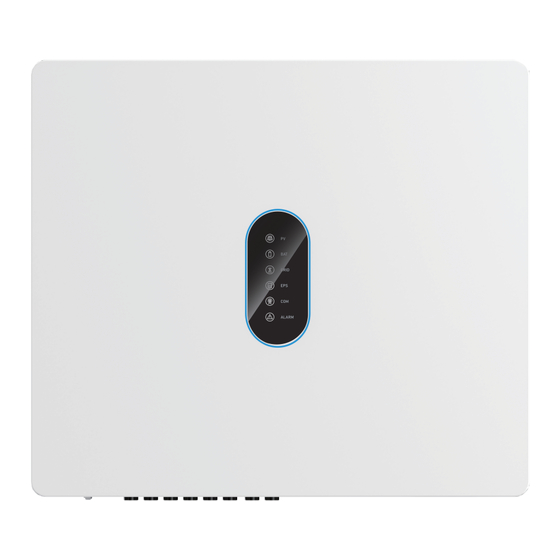
Product Information 2.2 Product Appearance 2.2.1 Type 1: Inverter with LED Unit:mm LED Icon Description PV indicator BAT indicator GRID indicator BACKUP indicator COM indicator ALARM indicator The External View of ESS Inverter... - Page 11 Product Information The Bottom View of ESS Inverter Number Description PV switch PV Input Terminals Battery Connect Terminals COM1 Ports (RS485, BMS, DRMs/RCR, CT, NTC/DI/DO, RSD/RMO, PARAL) COM Port (WIFI/LAN) Grounding Terminal BACKUP Output Terminal GRID Output Terminal...
- Page 12 Product Information 2.2.2 Type 2: Inverter with LED and LCD Unit:mm LED Icon Description PV indicator BAT indicator GRID indicator BACKUP indicator COM indicator ALARM indicator LCD Details The External View of ESS Inverter...
-
Page 13: Model Definition
Product Information The Bottom View of ESS Inverter Number Description PV switch PV Input Terminals Battery Connect Terminals COM1 Ports (RS485, BMS, DRMs/RCR, CT, NTC/DI/DO, RSD/RMO, PARAL) COM Port (WIFI/LAN) Grounding Terminal BACKUP Output Terminal GRID Output Terminal 2.3 Model Definition The letters in the product model have the specific informations. -
Page 14: Installation
Installation Installation 3.1 Packing List After unpacking, please check the following packing list carefully for any damage or missing parts. If any damage or missing parts found, please contact the supplier for help. 2 32 5 35 8 38 11 12 13 14 16 17 19 21 24 25 Number Quantity... -
Page 15: Selecting The Mounting Location
Installation 3.2 Selecting the Mounting Location 3.2.1 Installation Environment Requirements a. The storage inverter protection class is IP66 and can be mounted indoors or outdoors. b. To ensure optimum operation and long service life, the ambient temperature should be -25℃~60℃. c. - Page 16 Installation 3.2.2 Mounting Requirements Mount the inverter vertically or tilted backward by max 15°. Never install the inverter in a wrong way. Always make the connection area downward. ≤15° Upright Lean back ≤15° Upside-down Horizontal 3.2.3 Installation Space Requirements To ensure the normal and easy operation of inverter, please reserve enough installation clearance around the inverter as the following figure shows.
-
Page 17: Mounting
Installation 3.3 Mounting Before mounting the inverter, you have to prepare expansion screws and security screw. Before drilling holes, ensure that there is electrical or other pipes buried in DANGER the walls to avoid risks. To prevent potential damages and injuries from inverter falling down, CAUTION please well-mounted the inverter on the mounting bracket. - Page 18 Installation Expansion bolts (M10;4 sets) A & B Screw the bolt out C & D 1-2 turns. 35N·m Min. 2 M6 security screw 2.5N·m...
-
Page 19: Electrical Connection
Electrical Connection 4. Electrical Connection This chapter shows the connection details of the inverter. The following illustration is for reference only. Ensure that inverter and all cables to be installed are completely powered DANGER off during whole installation and connection. Otherwise, high voltage may result in fatal injury. - Page 20 Electrical Connection Breakers recommendation: Inverter Battery Breaker Backup Breaker Grid Breaker ≥63A ≥63A 12KHB-D3 ≥80A ≥63A ≥63A 15KHB-D3 ≥63A ≥63A 20KHB-D3 ≥160A*1 (Single battery connected to ≥80A ≥80A 25KHB-T3 both BAT1 and BAT2); ≥80A*2 (Battery systems connected to ≥80A ≥80A...
- Page 21 Electrical Connection Non-parallel connection mode Ensure that inverter and all cables to be installed are completely powered DANGER off during whole installation and connection. Otherwise, high voltage may result in fatal injury. Backup Breaker Breaker PV Array Critical Load Grid Breaker Normal Load Breaker CT ratio:...
- Page 22 The specifications of main breaker and normal load breaker depend on household loads. For other breakers, please refer to the table below. Breakers recommendation: Inverter Battery Breaker Backup Breaker Grid Breaker ≥63A ≥63A 12KHB-D3 ≥80A ≥63A ≥63A 15KHB-D3 ≥63A ≥63A 20KHB-D3 ≥160A*1 (Single battery connected to ≥80A...
- Page 23 Electrical Connection Parallel connection mode - Scheme A (N=2) Ensure that inverter and all cables to be installed are completely powered DANGER off during whole installation and connection. Otherwise, high voltage may result in fatal injury. ③ ① Flow from grid to inverter Breaker Turn this switch...
- Page 24 The specifications of main breaker and normal load breaker depend on household loads. For other breakers, please refer to the table below. Breakers recommendation: Inverter Battery Breaker Backup Breaker Grid Breaker ≥63A ≥63A 12KHB-D3 ≥80A ≥63A ≥63A 15KHB-D3 ≥63A ≥63A 20KHB-D3 ≥160A*1 (Single battery connected to ≥80A...
- Page 25 Electrical Connection Parallel connection mode - Scheme B (3≤N≤10) Flow from grid to inverter Breaker ③ Inverter No.N ① Backup Breaker Turn this switch to “ON”. Grid Breaker PV Array ① ③ ③ ③ Inverter No.2 ① Backup Breaker Turn this switch to “1”.
- Page 26 The specifications of main breaker and normal load breaker depend on household loads. For other breakers, please refer to the table below. Breakers recommendation: Inverter Battery Breaker Backup Breaker Grid Breaker ≥63A ≥63A 12KHB-D3 ≥80A ≥63A ≥63A 15KHB-D3 ≥63A ≥63A 20KHB-D3 ≥160A*1 (Single battery connected to ≥80A...
-
Page 27: Grounding
Electrical Connection 4.1 Grounding A protective earth (PE) terminal is equipped at the side of the inverter. Please be sure to connect this PE terminal to the PE bar for reliable grounding. • The inverter must be well-grounded; otherwise, there may be electric shock risk. -
Page 28: Grid/Backup Connection
Electrical Connection 4.2 GRID/BACKUP Connection Before connecting the GRID/BACKUP terminal, ensure that both the AC terminal and the DC terminal are powered OFF and the PV switch is OFF. Otherwise there is a risk of high voltage shock. For GRID/BACKUP connection, please perform the following steps: Step 1 Assemble the AC connector and then insert AC connector into GRID/BACKUP port. - Page 29 Electrical Connection Step 2 Install the AC circuit breaker. An appropriate AC breaker(≥ 63A or ≥ 80A)should be installed between inverter and the GRID / BACKUP for safety: a. Before installing the AC circuit breaker, please confirm the AC breaker is working normally.
-
Page 30: Battery Connection
Before connecting battery, please install a separate DC breaker between inverter and battery which ensures that the inverter can be security disconnected during maintenance. 12KHB-D3 / 15KHB-D3 / 20KHB-D3 can be connected to only one battery system. The battery cable must be connected to BAT 1, as shown below. - Page 31 Electrical Connection Single battery system connected to BAT2 of the inverter. Single battery system connected to both BAT1 and BAT2 of the inverter. (In this mode, the battery communication cable can only be connected to BMS1 port.) Battery systems connected to BAT1 and BAT2 of the inverter respectively. (In this mode, please connect the BAT1 communication cable to BMS1 and BAT2 communication cable to BMS2 port correspondingly.)
- Page 32 Electrical Connection BAT+ Red Cable BAT- Black Cable ② ③ ① +0.5 A. Diameter -0.3 B. Cross Section 25mm² Hydraulic Pressure C. Strip Length ~10mm Crimper ⑥ ⑤ ④ DC Breaker ≥ 80A(Equipped by user) Ensure that the PV ≤ 3 M switch is OFF.
-
Page 33: Pv Connection
Electrical Connection PV Connection Please check polarity of PV connectors! If polarity reversed, do not try to disconnect any PV connector until the irradiance declines and the DC currents fall below 0.5 A! WARNING Only then disconnect the PV plugs and correct the polarity before reconnecting. -
Page 34: Ct Connection (Direct Connect)
Electrical Connection CT Connection (Direct connect) You can monitor usage with a CT (Current transformer). Before connecting to Grid, please install a separate AC breaker (≥100A; prepared by user) between CT and Grid which ensures that the inverter can be security disconnected during maintenance. -
Page 35: Communication Connection
Electrical Connection Communication Connection Communication interfaces are located on the bottom of the inverter: Interface Descriptions Lithium battery communication interface RS485 RS485 communication (monitor / meter) 6-pin terminal for grid/load current transformer DI/DO control 9-Pin Temperature sensor terminal of lead-acid battery DO control DRMs Demand response mode for Australia application... - Page 36 Electrical Connection 4.6.1 BMS Connection (Only for Lithium Battery) • For 12KHB-D3 / 15KHB-D3 / 20KHB-D3, please connect the cable to BMS1 port. Otherwise, BMS communication may fail. • For 25KHB-T3 / 30KHB-T3, when single battery system is connected to both BAT1 and BAT2, please connect the cable to BMS1 port to realize BMS communication.
- Page 37 Electrical Connection INVERTER: BATTERY: Inverter Battery(example) Definition Definition RS485_ A RS485_B GND_S CAN_H CAN_H CAN_L CAN_L GND_S CAN BUS connection principle: INVERTER BATTERY CAN_H CAN_H CAN_L CAN_L For BMS communication connection, please refer to the following steps: 1.2N·m Unscrew the waterproof cover. Loosen the nut on waterproof cover.
- Page 38 Electrical Connection 4.6.2 RS485 Connection (Monitoring / Meter) 6-Pin Terminal Configuration of Monitoring / Meter Communication Function Description Inverter Monitoring RS485 A1 (for Monitoring) Pin1(RS485 A1) RS485 A RS485 B1 (for Monitoring) Pin2(RS485 B1) RS485 B RS485 A1 (for Monitoring) Inverter Meter RS485 B1 (for Monitoring)
- Page 39 Electrical Connection 4.6.3 CT Connection CT cable connection overview Pin1,2,3,4,5,6 Description Color (L1) (L2) (L3) CT3- (L3) Black CT3+ (L3) CT2- (L2) Black CT2+ (L2) CT1- (L1) Black CT1+ (L1) For CT connection, please perform the following steps: 1.2N·m Unscrew the waterproof cover. Loosen the nut on waterproof cover.
- Page 40 Electrical Connection 4.6.4 DI/DO Connection(s) Function Description DO3+ DO3- The inverter reserves a DO relay controlling Function Description port(DO3), which supports connecting additional NO1 (Normal Open) contactors to enable/disable the loads, such as household loads etc. COM1 Take following application for example, when NC1 (Normal Close) the DO relay is ON, the loads will be enabled;...
- Page 41 Electrical Connection 4.6.5 NTC Connection for Lead-acid Battery (Optional) 1.2N·m Unscrew the waterproof cover. Loosen the nut on waterproof cover. Remove sealing plugs. Function Pin8 GND Pin9 NTC BAT+ Attach to the battery surface Temperature sensor...
- Page 42 Electrical Connection 4.6.6 DRMs Connection DRMs is a shortened form for “inverter demand response modes”. It is a compulsory requirement for inverters in Australia. Note: With DRMs connection, it is necessary to connect APP to inverter and then go to Console >...
- Page 43 Electrical Connection 4.6.7 RSD/RMO Connection(s) 4-Pin Terminal Configuration of RSD/RMO Communication Function +12V REMO_OFF Description For RSD/RMO connection, please perform the following steps: 1.2N·m Unscrew the waterproof cover. Loosen the nut on waterproof cover. Remove sealing plugs. Threaded sleeve Cables Another inverter side Seal...
- Page 44 Electrical Connection 4.6.8 Parallel Communication Connection 4-Pin Terminal Configuration of parallel Communication Function GND_S PARA_SYNC CAN_L CAN_H Description For parallel communication connection, please perform the following steps: 1.2N·m Unscrew the waterproof cover. Loosen the nut on waterproof cover. Remove sealing plugs. Threaded sleeve Cables...
- Page 45 Electrical Connection Parallel communication cable connection overview Inverter No. 1 Inverter No. 2 Inverter No. N Turn the switch to “ON”. Turn the switch to “1”. Turn the switch to “ON”. It is necessary to turn the matched resistance switch of inverter No. 1 and inverter No. N to “ON” and turn the matched resistance switch of others to “1”...
- Page 46 Electrical Connection 4.6.9 WiFi/LAN Module Connection (Optional) For details, please refer to the corresponding Module Installation Guide in the packing. The appearance of modules may be slightly different. The figure shown here is only for illustration. Unscrew and remove the cover. Insert the module firmly.
-
Page 47: System Operation
System Operation System Operation 5.1 Inverter Working Mode The inverter supports several different working modes. 5.1.1 Self-consumption Mode Go to Console > Hybrid Setting > Work mode page, and select Self-consumption mode. Under Self-consumption mode, the supply priority of PV power will be Load > Battery > Grid, that means the power generated by PV system gives priority to local loads. - Page 48 System Operation b) Limited PV power When the PV energy is not enough to cover all consumption, the PV energy will be entirely used by loads, and the insufficient part will be supplied by battery. Then still insufficient parts will be supplied by grid.
- Page 49 System Operation 5.1.2 Feed-in Priority Mode Go to page , and select Console > Hybrid Setting > Work mode Feed-in priority mode Under this mode, Under Self Used mode, the supply priority of PV power will be Load > Grid > Battery, that means the power generated by PV system gives priority to local loads, the excess power will be fed into the grid first, then the remaining power charges the battery.
- Page 50 System Operation c) No PV Input The inverter will first discharge the battery power for home load consuming when no PV input (such as in the evening or some cloudy or rainy days). If the battery power is not enough, the load will be supplied by the grid..
- Page 51 System Operation 5.1.3 Back-up Mode Go to Console > Hybrid Setting > Work mode page, and select Back-up mode. Under this mode, the supply priority of PV power will be Battery > Load > Grid. This mode aims at fast battery charging. You can set whether to allow AC charging or not. Forbid AC Charging In this mode, the battery can be charged only with PV power, and the charging power varies with PV power.
- Page 52 System Operation Allow AC Charging In this mode, the battery can be charged both with PV and AC. a) Wealthy PV Power When PV energy is sufficient, PV charges the battery first, then meets the load, and the rest is fed into the grid.
- Page 53 System Operation 5.1.4 Off Grid Mode When the power grid is cut off, the system automatically switches to Off Grid mode. Under off-grid mode, only critical loads are supplied to ensure that important loads continue to work without power failure. Under this mode, the inverter cannot work without the battery.
- Page 54 System Operation b) Limited PV power When PV energy is limited, BACKUP loads are first powered by PV and then supplemented by battery. BACKUP is the sequence of BACKUP load consumption. Under this mode, please complete the output voltage and frequency settings.
- Page 55 System Operation 5.1.5 On-grid Unbalanced Output 1) The normal load is single phase. 2) The three phases of normal load are different or unbalanced. This is the best scheme to meet your needs. Three Phase ESS Inverter Power Generation Date Monitoring Platform WiFi/LAN, RS485 Meter...
- Page 56 System Operation 5.1.6 Back-up Unbalanced Output 1) The critical load is single phase. 2) The three phases of critical load are different or unbalanced. This is the best scheme to meet your needs. Three Phase ESS Inverter Power Generation Date Monitoring Platform WiFi/LAN, RS485 Meter...
-
Page 57: Startup/Shutdown Procedure
System Operation Startup/Shutdown Procedure 5.2.1 Startup Procedure Check and confirm the installation is secured and that the system is well-grounded. Ensure that all connections (AC, battery, PV etc.) are correct, parameters and configurations conform to relevant requirements. AC Frequency 50/60Hz PV Voltage 160~950V Battery Voltage 120~800V... -
Page 58: Commissioning
Commissioning Shutdown Procedure ⑤ PV Switch ‘OFF’ AC Circuit ③ Breaker ‘OFF’ Battery Circuit ④ BACKUP Circuit ② Breaker ‘OFF’ Breaker ‘OFF’ ① Go to APP; enter Quick Setup; and shutdown the inverter. After the inverter is powered off, the remaining electricity and heat may still cause electric shock and body burns. -
Page 59: User Interface
User Interface 7. User Interface 7.1 LED This section describes the LED panel. LED indicator includes PV, BAT, GRID, BACKUP, COM, ALARM indicators. It includes the explanation of indicator states and summary of indicator states under the running state of the machine. LED Indicator Status Description PV input is normal. - Page 60 User Interface BACKUP ALARM Grid Details Code PV normal ● ◎ ◎ ◎ ◎ ○ No PV ○ ◎ ◎ ◎ ◎ ○ PV over voltage PV under voltage PV irradiation weak ★ ◎ ◎ ◎ ◎ ○ PV string reverse PV string abnormal On grid ◎...
- Page 61 User Interface BACKUP ALARM Grid Details Code Communication loss (Inverter - BMS1) Communication loss (Inverter - BMS2) ◎ ◎ ★ ◎ ◎ ○ Battery1 reversed Battery2 reversed ◎ ◎ ◎ ● ◎ ◎ BACKUP output active BACKUP output inactive ◎ ◎...
- Page 62 User Interface Grid BACKUP ALARM Details Code Software incompatibility Internal storage error Data inconsistency ◎ ◎ ◎ ◎ ◎ ● Inverter abnormal Boost abnormal Dc-dc abnormal Battery communication cable configuration error ◎ ◎ ★ ◎ ◎ ○ Battery power cable configuration error Remark: Light on...
- Page 63 User Interface 7.2 LCD Description LCD screen is optional for this series of inverters. If you choose a LCD screen, the following introduction will help you understand the function of each icon displayed. Menu Structure Overview Communication Date and Time Status Warning Work Mode Status...
- Page 64 User Interface Example: Icon Display Area E-Day E-Tot al E-Day E-Tot al Date Unit K kWh Date Display Area Display Area Example: Icon Display Area Phase Date Unit Date Display Display Display Area Area Area Icon Introduction-2 The PV icon represents the power of PV. The Battery icon represents the current battery charge percentage or the voltage of battery.
- Page 65 User Interface Icon Status Description Icon Name Light Description Any PV voltage exists ( it should be higher than the Min. PV Startup Voltage) . PV Voltage is lower than the Min. PV Startup Voltage. Grid Voltage and frequency are normal. Grid Grid over-voltage / under-voltage / over-frequency / under-frequency occurs.
-
Page 66: App Setting Guide
User Interface 7.3 App Setting Guide 7.3.1 Download App Scan the QR code on the inverter to download the APP. Download APP from the App Store or Google Play. Note: The APP should access some permissions such as the device’s location. You need to grant all access rights in all pop-up windows when installing the APP or setting your phone. - Page 67 User Interface 7.3.3 Local Login To login the APP, please perform the following steps: 1. Enable the Bluetooth on your own phone and open the APP, then click the Bluetooth Connection. 2. To connect the inverter, please choose one of the following three ways: Scan machine SN barcode Enter SN Manual connection...
- Page 68 User Interface 2. Read tips on the screen carefully before choosing the Wi-Fi SSID and entering the Wi-Fi password. Then click START THE CONFIGURATION and wait for Wi-Fi router loading successfully. Then click Next. Note: Please use the 2.4G network frequency band for configuration. XXXXXXXX Step1 Set parameters the inverter to connect to the router.
- Page 69 User Interface 4. Set parameters for the inverter to connect to the power limit. Then click the Next. XXXXXXXX Step3 Set parameters for the inverter to connect to the power limit. Power control CT senser Meter location On Grid Power flow direction From grid to inverter Maximum feed in grid power (W) 30000...
- Page 70 User Interface 6. Please click the button to turn on the inverter. XXXXXXXX Step5 Please click the button below to turn on the inverter. Previous Quick Setup Chart Home Console...
- Page 71 User Interface ▪ Chart The power chart is showed by Day, Month and Year in our APP. Data curves in the following figures are only for illustration. Query Daily Data Go to Chart > page. It will show the Daily Production or Consumption Curve in this page. You can click anywhere on the graph to see the energy value of any time.
- Page 72 User Interface Query Monthly Data Go to Chart > Month page. It will show the Monthly Production or Consumption Curve in this page. You can click anywhere on the graph to see the energy value of any month. XXXXXX PV generation capacity Load consumption capacity Feed-in grid capacity Grid capacity...
- Page 73 User Interface Query Yearly Data Go to Chart > Year page. It will show the Annually Production or Consumption Curve in this page. You can click anywhere on the graph to see the energy value of any year. XXXXXX PV generation capacity Load consumption capacity Feed-in grid capacity Grid capacity...
- Page 74 User Interface ▪ Home In this page, you can view the basic information of inverter. Click “ ” to display the warning message. XXXXXXXX XXXXXXXX 19.1kWh 494kWh 19.1kWh 494kWh E-Today E-Total E-Today E-Total Self-consumption mode Self-consumption mode 2.71kW 2.71kW 405W 405W 2.21kW 2.21kW...
- Page 75 User Interface ▪ Console In this page, you can view the basic information like some version information, do some maintaining operations like turn off/on the inverter and manage data. XXXXXXXX XXXXXXXX 19.1kWh 494kWh E-Today E-Total Self-consumption mode 2.71kW 405W 2.21kW 0.00W 60.0W SOC: 40%...
- Page 76 User Interface Maintenance In this page, you can do some maintaining operations like turn off/on the inverter and manage data. Console page, click Maintenance. XXXXX XXXXX XXXXX XXXXX XXXXX...
- Page 77 User Interface Access Management In this page, you can switch the login permission. Console page, click Access Management > Change User page. Communication Setting In this page, you can set or change the parameters of communication settings: WiFi Setting, RS485 Setting and Ethernet Setting.
- Page 78 User Interface Grid Parameters In this page, you can set or change the parameters of Grid side. Console page, click Grid Parameters. Note: Setting/modifying these parameters requires logging into an administrator account.
- Page 79 User Interface Feature Parameters In this page, you can set or change the feature parameters, as shown in the figure. Console page, click Feature Parameters. Note: Setting/modifying these parameters requires logging into an administrator account. Power Limit In this page, you can set or change the parameters of power limit. Console page, click Power Limit...
- Page 80 User Interface Reactive Power Control In this page, you can set or change the Reactive Power Control parameters. Console page, click Reactive Power Control. Note: Setting/modifying these parameters requires logging into an administrator account.
- Page 81 User Interface Autotest To perform autotest, please perform the following steps: 1. In Console page, click Grid Parameters > Standard Code,then select the IT (CEI 0-21) or IT (CEI O-21 ACEA). 2. Back to Console page. Refresh the page and enter the Autotest page to click START.
- Page 82 User Interface Other Setting In this page, you can set other setting parameters. Console page, click Other Setting. Other Setting Date and Time ����-��-�� ��:��:�� AFD Function AFD Reset Enable DRM Function DRM Function When the DRMs set up. Grid Voltage type Three-phase L-N voltage...
- Page 83 User Interface Hybrid Setting In this page, you can set Hybrid Setting parameters. Console page, click Hybrid Setting. Note: Setting/modifying these parameters requires logging into an administrator account. Hybird Setting Work mode (Self-consumption mode) Battery Backup Load(Enable) Other Work mode The inverter supports three work modes: self-consumption mode, feed-in priority mode and Back-up mode.
- Page 84 User Interface Time-based Control setting: In Work mode page, you can also find time-based control function. This function is designed to control the time setting of charging and discharging the inverter. You can set the following parameters based on your requirements: - Charge and discharge frequency: one time or daily - Charging start time: 0 to 24 hours - Charging end time: 0 to 24 hours...
- Page 85 User Interface Battery Battery page, information including battery parameters, charging and discharging management and grid will be listed. Enter corresponding information if necessary. Since there are two groups of battery connect terminals, for 25 KHB-T3 / 30 KHB-T3, it is necessary to set battery connection type on APP and make sure that the connection methods of power port and BMS port are correct by following the table below before powering on the inverter.
- Page 86 User Interface Backup Load Backup Load page, if enabling Backup Output, you can set parameters including the range of backup output voltage and Min. initiation / startup battery capacity when off-grid. Be aware of the danger of electric shock! When the power grid is connected and the inverter is turned on, even if the Backup Output DANGER option is not enabled, the Backup port of the inverter still has AC...
-
Page 87: Maintenance
Maintenance 8. Maintenance Before maintaining and commissioning inverter and its peripheral distribution unit, switch off all the charged terminals of the inverter and wait at least 10 CAUTION minutes after the inverter is powered off. 8.1 Routine Maintenance Maintain Content Maintenance Items Check Content Interval... -
Page 88: Inverter Troubleshooting
Maintenance 8.2 Inverter Troubleshooting When the inverter has an exception, its basic common warning and exception handing methods are shown below. Code Alarm Information Suggestions 1. If the alarm occurs occasionally, possibly the power grid voltage is Grid over voltage abnormal for a short time, and no action is required. - Page 89 Maintenance Code Alarm Information Suggestions 1. If the alarm occurs occasionally, possibly the power grid voltage is abnormal for a short time, and no action is required. Inverter over dc-bias current 2. If the alarm occurs repeatedly, and the inverter fails to generate power, contact the customer service center.
- Page 90 Maintenance Alarm Information Suggestions Code 1. If the alarm occurs occasionally, the inverter can be automatically Internal communication recovered and no action is required. error 2. If the alarm occurs repeatedly, the inverter cannot work properly. Please contact the customer service center. 1.
- Page 91 Maintenance Code Alarm Information Suggestions 1. If the alarm occurs occasionally, the inverter can be automatically recovered and no action is required. Battery1 under voltage 2. Check the communication line connection between BMS and inverter (lithium battery). 3. The battery is empty or the battery voltage is lower than the SOC cut- off voltage.
- Page 92 Maintenance Code Alarm Information Suggestions 1. Check whether the communication cables between BACKUP, electricity Internal communication meter and inverter are well connected and whether the wiring is correct. loss(E-M) 2. Check whether the communication distance is within the specification range. 3.
- Page 93 Maintenance Code Alarm Information Suggestions 1. Check the parallel cable connections. Parallel ID warning 2. Contact the customer service center. 1. Check the parallel cable connections. Parallel SYN signal 2. Contact the customer service center. warning Parallel BAT abnormal Connect the battery. Connect the battery.
-
Page 94: Removing The Inverter
Technical Specification 8.3 Removing the Inverter Before removing DC input connector, double check DC input switch is turned WARNING to OFF to avoid inverter damage and personal injury. Perform the following procedures to remove the inverter: 1. Disconnect all cables from the inverter, including communications cables, DC input power cables, AC output power cables, and PGND cable, as shown below. -
Page 95: Technical Specifications
Maintenance 9. Technical Specification Model SE 12KHB-D3 SE 15KHB-D3 SE 20KHB-D3 SE 25KHB-T3 SE 30KHB-T3 Input (PV) Max. PV Input Power 18,000W 22,500W 30,000W 37,500W 45,000W Max. PV Voltage 1,000V Start-up Voltage 150V MPPT Operating Voltage Range 160V-950V MPPT Voltage Range at Rated Power... - Page 96 Maintenance Model SE 12KHB-D3 SE 15KHB-D3 SE 20KHB-D3 SE 25KHB-T3 SE 30KHB-T3 Protection Protection Category Class I DC Switch Anti-islanding Protection AC Overcurrent Protection DC/AC Overvoltage Protection DC Type II, AC Type III AC Short Circuit Protection DC Reverse Protection...
Need help?
Do you have a question about the 12KHB-D3 and is the answer not in the manual?
Questions and answers