Table of Contents
Advertisement
Quick Links
Advertisement
Table of Contents

Related Manuals for Senergy 16KTL-DL3


Summary of Contents for Senergy 16KTL-DL3
- Page 1 Ver. 01 17KTL~30KTL-D3 16KTL/18KTL-DL3...
-
Page 2: Table Of Contents
Contents Forward Application Model Intended Audience Symbol Conventions 1 Safety Precautions 1.1 Personnel Safety 1.2 The PV Inverter Protection 1.3 Installation Safety 1.4 Electrical Connections 1.5 Operating and Commissioning 1.6 Maintenance 1.7 Additional Information 2 Overview of the Inverter 2.1 Functional Models 2.1.1 Function 2.1.2 Model Description 2.2 Network Application... - Page 3 4.4.2 Installation Mode Requirements 4.5 Support-mounting the Inverter 4.6 Installation Self-check 5 Electrical Connections 5.1 Connecting Protection Ground (PGND) Cables 5.1.1 Preparation 5.1.2 Wiring Procedures 5.2 Connecting AC Output Cables 5.2.1 Preparation 5.2.2 Procedure of Connecting AC Cables 5.3 Connecting the PV Strings 5.3.1 Preparation 5.3.2 Procedure of connecting the PV Strings 5.4 Connecting Communications Cables...
-
Page 4: Forward
Please read through the manual carefully before installing and using the inverter, and keep the manual well for future reference. Application Model Grid-tied PV string inverter 16KTL-DL3)/18KTL-DL3)/17KTL-D3/20KTL-D3/22KTL-D3 25KTL-D3/28KTL-D3/30KTL-D3 Intended Audience This user manual is intended for photovoltaic (PV) inverter operating personnel and qualified electrical technicians. -
Page 5: Symbol Conventions
Symbol Conventions Safety symbols used in this manual, which highlight potential safety risks and important safety information, are listed as follows: Symbol Description Indicates an imminently hazardous situation which, if not correctly DANGER followed, will result in serious injury or death. Indicates a potentially hazardous situation which, if not correctly WARNING followed, could result in serious injury or death. -
Page 6: Safety Precautions
Please read the User Manual carefully before installing the PV inverter; NOTICE warranty or liability will be void from Senergy if damage is caused by installation faults. a. Ensure there is no electronical connections around ports of the PV inverter before installing;... -
Page 7: Electrical Connections
1.4 Electrical Connections Before installing the inverter, check all electrical ports to ensure no damage and no short circuit. Otherwise personal casualty and/or fire DANGER will occur. a. Input terminals of the PV inverter apply only to input terminals of PV String; do not connect any other DC source to the input terminals. -
Page 8: Additional Information
Check the relevant safety and performance of the inverter; rectify any faults that may compromise the inverter security performance before restarting the inverter. 1.7 Additional Information To avoid any other unforeseeable risk, contact Senergy immediately, if NOTICE there is any issue found during operation. -
Page 9: Overview Of The Inverter
2 Overview of the Inverter This chapter introduces the inverter and describes its functional model, network application, appearance, dimensions, and working process etc. 2.1 Functional Models 2.1.1 Function This series is a three-phase grid-tied PV string inverter (transformer less) that converts the DC power generated by PV strings into AC power and feeds the power into power grid. -
Page 10: Outline And Dimensions
PV strings inverter AC Distribution Unit low-voltage power grid Figure 2.2 a low-voltage grid-tied PV power system These series support the power grid modes TN-S, TN-C, TN-C-S, and TT, as shown in Figure 2.3. Inverter Inverter Inverter Inverter TN-S TN-C TN-C-S Figure 2.3 Power grids supported by these series inverters 2.3 Outline and Dimensions... -
Page 11: Outline
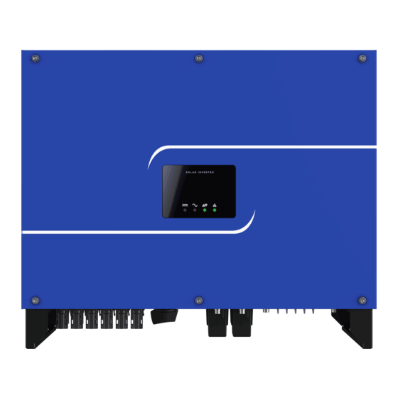
2.3.2 Outline Figures 2.5 to 2.7 show the outline of the inverters as follows: 1. PV Indicator 2. Grid Indicator 3. COM Indicator 4. Warning Indicator (optional) 5. LCD Figure 2.5 The front view and amplification effect of LED indicator area Install the backboard Figure 2.6 The rear view of PV inverter PV Strings connectors... -
Page 12: Working Modes
2.4 Working Modes Three working modes of the inverter are shown as follows: standby, operating, and shutdown. Table 2.1 shows the conditions for the inverter to switch between working modes. Modes Description The PV inverter enters the standby mode when >the input voltage of PV Strings can enable auxiliary power supply to run, but cannot meet the inverter operation requirements. -
Page 13: Storage
3 Storage This chapter describes the storage requirements for the inverter. The following storage instructions apply if the PV inverter will not be deployed immediately: > Do not unpack the inverter (put desiccant in the original box if the PV inverter is unpacked). >... -
Page 14: Installation
4 Installation Do not install the inverter on flammable building materials or in an DANGER area that stores flammable or explosive materials. Do not install the inverter in a place where personnel are likely to CAUTION come into contact with its enclosure and heat sinks to avoid electrical shock / burn. -
Page 15: Moving The Inverter
If any damage mentioned above is found, contact the dealer NOTICE immediately. 4.2 Moving the Inverter After checking the outer packing, move the PV inverter to the designated installation position horizontally, as shown in Figure 4.2. Figure 4.2 Moving the inverter The inverter is relatively heavy! To prevent device damage and personal CAUTION injury, arrange two people to move the inverter and handle with care. -
Page 16: Compliance And Safety Symbols
4.3.2 Compliance and Safety Symbols Safety symbol Description Electrical shock! There are residual voltages in the PV inverter. It needs 10 minutes 10min to finish discharge. The PV inverter must not be touched when in operation. Its enclosure and heat sinks are extremely hot. Electrical shock! This part is charged. - Page 17 The inverter must be installed in a well ventilated environment to ensure good heat dissipation. The inverter must be free from direct exposure to sunlight, rain, and snow to extend its service life. It is recommended that the inverter be installed in a sheltered place. If no shelter is available, build an awning, as shown in Figure 4.3.
- Page 18 >500 >1000 >200 >200 >600 the front view the lateral view Figure 4.4 Installation Space Requirements (unit: mm) When installing multiple inverters, install them along the same line (as shown in Figure 4.5) if sufficient space is available, and install them in triangle mode (as shown in Figure 4.6) or in stacked mode (as shown in Figure 4.7) if no sufficient space is available.
- Page 19 Figure 4.6 Installation in triangle mode (unit: mm) Figure 4.7 Installation in stacked mode (unit: mm) The clearance between multiple inverters must be increased to NOTICE ensure proper heat dissipation when they are installed in a hot area.
-
Page 20: Installation Mode Requirements
4.4.2 Installation Mode Requirements Install the inverter upright or at a maximum back tilt of 15 degrees to facilitate heat dissipation. Below are some correct / wrong installation modes, as shown in Figure 4.8&4.9. The correct installation mode upright back tilt Figure 4.8 The correct installation mode The wrong installation mode Horizontally... -
Page 21: Installation Self-Check
, as shown Step 2 Mount the inverter on the rear panel and keep them aligned with each other in Figure 4.11. Figure 4.11 Mounting the inverter Step 3 Tighten one screw at the right of the inverter and the retaining screw on the rear panel, and ensure that they are secured, as shown in Figure 4.12. -
Page 22: Electrical Connections
5 Electrical Connections Before performing any electrical connections, ensure that both DC and AC Switches are OFF. Otherwise, fatal injury can occur due to DANGER the high voltage caused from AC and DC cables. Grounding the PV Strings needs below prerequisites: CAUTION An isolation transformer must be installed on the AC side of each inverter;... -
Page 23: Wiring Procedures
It is recommended that the ground cable be connected to a nearby ground position. For a system with multiple inverters connected in NOTE parallel, connect the ground points of all inverters to ensure equipotential connections. 5.1.2 Wiring Procedures Step 1 Remove an appropriate length of the insulation layer from the PGND cable using a wire Stripper;... -
Page 24: Connecting Ac Output Cables
5.2 Connecting AC Output Cables 5.2.1 Preparation The AC power cable and AC terminals have been prepared with below requirements. a. AC power cable: Outdoor multi copper-cores cables are recommended. Table 5.1 describes the specifications. Cable Outer Cross-sectional Area (mm ) Diameter (mm) Inverter Model Cable type... -
Page 25: Procedure Of Connecting Ac Cables
5.2.2 Procedure of Connecting AC Cables Step 1 Remove an appropriate length of the jacket and insulation layer from the AC output cable as shown in Figure 5.4. specification:M6 L2=L1+(2mm-3mm) 120(recommend) Figure 5.4 Stripped length (unit: mm) Step 2 Insert the exposed core wires into the crimp area of the OT terminal and crimp them using hydraulic pliers. - Page 26 Step 3 Loosen the four screws lock on AC OUTPUT door, and connect L1, L2, L3, N and PE through AC OUTPUT terminal cover to the terminal block, use a screw driver to tighten screws to a torque of 3N·m, as shown in Figure 5.6. L1 L1 L1 L2 L2 L2 L3 L3 L3 N N N PE PE PE...
-
Page 27: Connecting The Pv Strings
5.3 Connecting the PV Strings PV Strings connection needs below prerequisites; otherwise, an DANGER electrical shock can occur. PV modules generate electric energy when exposed to sunlight and can create an electrical shock hazard. Therefore, when connecting the PV modules, shield them with opaque cloth. Before connecting DC input power cables, ensure that the voltage on the DC side is within the safe range and that the DC SWITCH on the inverter is OFF. -
Page 28: Preparation
5.3.1 Preparation PV Strings DC input cable and connectors have been prepared with below requirements: a. Route connecting for the installation of PV strings and the inverter is shown in Table 5.2 Input Route Number of Input Route Inverter model Connected to any route Connected to routes 1 &... -
Page 29: Procedure Of Connecting The Pv Strings
c. Connectors of PV Strings: Positive and negative DC input connectors are used, as shown in Figure 5.8 and Figure 5.9. the insulation layer locking nut the insulation layer locking nut Figure 5.8 Positive connector compositions Figure 5.9 Negative connector compositions Positive and negative metal connectors are packed with positive and NOTE negative connectors respectively when shipped out. - Page 30 Step 2 Insert the exposed areas of the positive and negative power cables into the metal terminals of the positive and negative connectors respectively and crimp them using a crimping tool, as shown in Figure 5.11. Figure 5.11 Crimping a metal connector Step 3 Insert the crimped positive and negative power cables into the corresponding positive and negative connectors until a "click"...
-
Page 31: Connecting Communications Cables
800 00 RANGE MAXMIN Hz % h FE FUSED FUSED Figure 5.14 Checking the voltage of every route Strings Step 6 Insert the positive and negative connectors into their corresponding terminals of the inverter until a "click" sound is heard, as shown in Figure 5.15. Figure 5.15 Connecting to the inverter Step 7 After connecting the PV strings, ensure that all connectors are in position by checking for resistance when a slight pull is applied. - Page 32 RS485 For more details, refer to RS485 switching Product Application Manual. You can choose and buy WIFI / GPRS / RS485 communication modules from Senergy. NOTE WIFI / GPRS / RS485 / SE Touch User Manual are available from http://www.senergytec.com.
-
Page 33: Connecting Rs485 Communications Cables
RS485 communications mode (for multiple inverters) Inverter Data Logger Router/Modem Cloud Sever RS485 IN RS485 OUT Terminal Device Figure 5.17 RS485 communications for multiple inverters 5.4.2 Connecting RS485 Communications Cables Step 1 Remove an appropriate length of the insulation layer from the cable using a wire stripper, as shown in Figure 5.18. -
Page 34: Setting Rs485 Communications Address
Step 5 Connect RS485 male terminal with its female terminal, Tighten the locking caps to a torque of 8 N·m as well as waterproof cable connectors. To prevent corrosion, apply silica gel or fireproof mud to the terminal or interface after connecting external PGND cables, AC cables, NOTE RS485 port, and Ethernet port. -
Page 35: Installation Verification
Step 3 Check the Modbus address in Figure 5.22, the default address is 1, long click to revise the address and save it, the inverter at same RS485 bus must be set a unique address. Figure 5.22 Check the Modbus address 5.5 Installation Verification Check the following items after the inverter is installed according to Table 5.5. -
Page 36: System Operation
6 System Operation 6.1 Powering ON the Inverter Step 1: Switch ON the AC circuit breaker. Step 2: Set the DC SWITCH of the inverter to ON. Step 3: Observe statuses of LED indicator lights on the inverter according to Table 7.2. When LED status lights display the inverter has entered NOTE grid-connecting, it means the inverter is operating well. -
Page 37: User Interface
7 User Interface Display screen of inverter is composed of LED indicator and LCD (LCD is optional for some models of inverter). LED indicator includes PV Indicator, Grid Indicator, COM Indicator, and Warning Indicator. 1. PV indicator 2. Grid indicator 3. - Page 38 LCD Screen Warning Date Status Meter Output 1) COM When WIFI/GPRS/Bluetooth is transferring data, icon will be ON, while no data transmission, the icon will be off after 10s. When RS485 is transferring data, icon will be ON, while no data transmission, the icon will be off after 10s.
- Page 39 5) Meter Normal status: today and total energy, MPPT voltage and current are showed in turn. Standby status: counter down value before inverter start up. Any status: setting parameters via APP, the screen keep for 5 seconds. 6) Output Normal status: output power, grid voltage and current are showed in turn.
- Page 40 Grid absent Grid over frequency Grid under frequency Grid unbalance PV over voltage PV under voltage Weak radiation Strings abnormal Inverter over temperature Fan abnormal Insulation resistance abnormal Leakage current abnormal Strings reverse Control power abnormal DC bias current abnormal Inverter relay abnormal Leakage current HCT abnormal System fault...
-
Page 41: Maintenance
8 Maintenance Before maintaining and commissioning inverter and its peripheral distribution unit, switch off all the charged terminals of the inverter WARNING and wait at least 10 minutes after the inverter is powered off. 8.1 Routine Maintenance Maintain Maintenance Check Item Check Content content Interval... -
Page 42: The Inverter Troubleshooting
8.2 The Inverter Troubleshooting When inverter enters in shutdown mode abnormally, the alarm light is illuminated. Table 8.2 describes the troubleshooting measures for common fault alarms in the inverter. Alarm Name Causes Measures Recommended Grid 1. If the alarm occurs accidentally, possibly the power grid is abnormal accidentally. - Page 43 The insulation resistance against the ground at the 1. If the alarm occurs accidentally, possibly the external input side circuits are abnormal accidentally. The inverter Residual decreases automatically recovers to the normal operating status Current during the inverter after the fault is rectified. Abnormal operation, which 2.
-
Page 44: Removing The Inverter
remote monitor If modem or other data logger is used, please reboot Communications displays zero it; if still does not work after rebooting, contact your outage power generation dealer. remote monitor Output switch Check if DC switch is damaged, and if not, switch it to displays no output tripping ON. - Page 45 Step 2: Remove the inverter from the rear panel. Step 3: Remove the rear panel. Before removing DC input connector, double check DC input switch WARNING is turned to OFF to avoid inverter damage and personal injury. Fan Maintenance 25K/28K/30K there are external FAN, check periodically heat sink and the inlet / outlet of external FAN, clean them, and ensure that they are free from dust and blockage.
-
Page 46: Quality Guarantee
9.2 Liability Waiver Warranty or liability will be void if damage is caused from below operations / situations. If customer asks for maintenance service, Senergy can, at its discretions, provide paid service. 1) The warranty period expired; 2) The damage caused during transit;... -
Page 47: Disposal Of The Inverter
10 Disposal of the Inverter The PV inverter and its packing case are made from environmental protection material. If the inverter service life has expired, do NOT cut it away with household garbage; dispose the inverter in accordance with local rules for disposal of electrical equipment waste. -
Page 48: Technical Specifications
11 Technical Specifications Inverter Model 16KTL-DL3 18KTL-DL3 17KTL-D3 20KTL-D3 22KTL-D3 25KTL-D3 28KTL-D3 30KTL-D3 Efficiency Max. efficiency 98.00% 98.30% 97.70% 98.00% European efficiency Input Max. input power 24,700W 27,000W 36,000W 45,000W Max. input voltage 800V 1000V Max. input current 81A (2*40.5A) 54A (2*27A) 81A (2*40.5A) - Page 49 Display & Communications Display LED indicator light/LCD(optional) Communications RS485,Bluetooth, WIFI(optional ),GPRS(optional) Standards Compliance Safety certification IEC62109-1, IEC62109-2, NB/T 32004 Grid-tied IEEE 1547, IEC 61727, IEC62116 IEC61727, NB/T32004 Protection Supported: Input DC switch, Anti-islanding protection, low voltage ride-through, Output over current Protection, Output shirt circuit protection, Input reverse-connection protection, PV string fault detection, DC surge protection, AC surge protection, Insulation resistance detection, RCD detection Remark for sign *: To avoid potential risk, you are recommended to add following devices: a 15A/1000VDC PV...
Need help?
Do you have a question about the 16KTL-DL3 and is the answer not in the manual?
Questions and answers