
Related Manuals for Senergy Natural cooling Series


Summary of Contents for Senergy Natural cooling Series
- Page 1 Version: EN-UM-1.1 USER MANUAL Three-Phase Grid-Tied Solar Inverter 30K/40K/50K/60K LV25/30/36K...
- Page 2 History VERSION ISSUED COMMENTS 15-Jun.-23 First release 15-Nov.-23 Updated bracket 3.1 Packing Mounting.
-
Page 3: Target Group
Manual are for reference only. This Manual is subject to change without prior notice. (Specific products in kind prevail.) Target Group Inverters must be installed by qualified and professional electrical engineers. Scope Natural cooling series Fan cooling series 1 Fan cooling series 2 Fan cooling series 3 50KTL-Q3/G2... -
Page 4: Table Of Contents
CONTENTS Preface About This Manual Target Group Scope Conventions 1. Safety 1.1 Symbols Used 1.2 Safety Precautions 2. Product Introduction 2.1 Overview 2.2 Product Appearance 3. Unpacking and Storage 3.1 Unpacking and Check 3.2 Storage Inverter 3.3 Identify Inverter 4. Installation 4.1 Selecting the Mounting Location 4.2 Mounting 5. - Page 5 6. Startup/Shutdown Procedure 6.1 Inspection 6.2 Startup Procedure 6.3 Shutdown Procedure 7. User Interface 7.1 LED 7.2 LCD 8. Troubleshooting and Maintenance 8.1 Inverter Troubleshooting 8.2 Maintenance 9. Technical Specifications...
-
Page 6: Safety
Safety 1 Safety Before using the inverter, please read all instructions and cautionary markings on the unit and in this Manual. Put this Manual in a place where you can take it easily. Our inverter strictly conforms to related safety rules on design and test. -
Page 7: Safety Precautions
Safety 1.2 Safety Precautions Installation, maintenance and connection of inverters must be performed by qualified personnel, in compliance with the electrical standards, wiring rules and requirements of local power authorities and/or companies. To avoid electric shock, DC input and AC output of the inverter must be terminated at least 10 minutes before performing any installation or maintenance. -
Page 8: Product Introduction
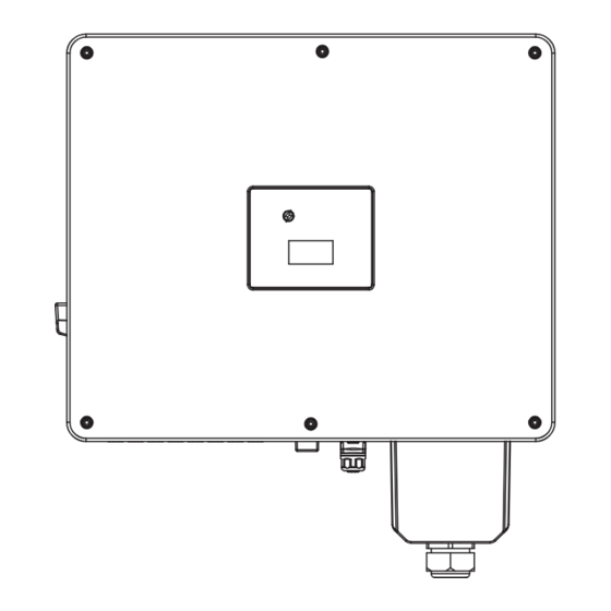
Product Introduction 2 Product Introduction 2.1 Overview The three-phase grid-tied solar inverter converts the direct current (DC) generated by PV panels into three-phase alternating current (AC) and is delivered to the grid. This series of inverter is an important part of PV system and it is suitable for household use, commercial roof, fishing light, and agricultural light and more scenarios. - Page 9 Product Introduction 50K: 254.8mm 223.3mm 635mm 60K: 264.5mm 233mm 635mm Three-Phase Grid-Tied Solar Inverter 4...
- Page 10 Product Introduction Fan cooling series 1 Natural cooling series Fan cooling series 2 Fan cooling series 3 Number Description DC Switch LED indicator LCD Screen (optional) External ground points PV terminal Vent valve WIFI module communication port (COM1) Reserved communication port (COM2/3)
-
Page 11: Unpacking And Storage
Unpacking and Storage 3 Unpacking and Storage 3.1 Unpacking and Check Complete test and strict inspection before the inverter is sent out. When receiving the inverter, check that the packing materials are intact. After unpacking, examine the PV inverter and its fittings for damage and check that the deliverables are complete. -
Page 12: Storage Inverter
Product Introduction 3.2 Storage Inverter If the inverter is not used immediately, please keep the inverter in a specific environment according to the following: Do not unpack the inverter and put desiccant in the original box if the PV inverter is unpacked. Store temperature range: -25°C ~ +60°C;... -
Page 13: Installation
Installation 4 Installation After checking the outer packing, move the PV inverter to the designated installation position horizontally. 1. Please place the inverter horizontally on the foam or other soft pads and ensure that the ports are free of load-bearing pressure to avoid inverter damages or scratches. CAUTION 2. - Page 14 Installation 4.1.2 Mounting Requirements Mount the inverter vertically or tilted backward by max 15°. In order to facilitate the heat dissipation of the inverter. A wrong installation mode would cause the inverter to be damaged or unable to work NOTICE properly.
-
Page 15: Mounting
Installation Installation perspective schematic: 635mm 575mm 490mm 245mm 4.2 Mounting 4.2.1 Install the Mounting Bracket 4.2.1.1 Wall-Mounted Installation 1.The walls must be fireproof and non-flammable materials, otherwise there is a fire risk. DANGER 2.Before drilling holes ,check whether there are electric power pipes buried in the walls to avoid risks. - Page 16 Installation Step3 Insert the expansion bolts into the holes and secure them with a hammer. Then remove the nut, spring washer, and flat washer. Note: Do not remove the nut before performing this step. (M12 x 80mm;3 sets) Step4 Fix the mounting-bracket wiht the expansion bolts. Screw:3*M12, torque: 26N·m. 3x M12 26 N·m 4.2.1.2 (Optional) Bracket-Mounted Installation...
- Page 17 Installation 4.2.2 Install the Inverter Hook the inverter into the bracket accurately and tighten the screws at both sides. We recommend at least two persons to carry the inverter. min. 2 2x M6 3 N·m Handle tool is optional. Two sides To prevent damage of the inverter, please hang the inverter on the bracket CAUTION and confirm the reverse, do not loosen the handle until the inverter is fixed.
-
Page 18: Electrical Connections
Electrical Connection 5 Electrical Connection System Connection DANGER Before electrical connection, please ensure that both the AC and DC ends are powered off, otherwise there will be a high voltage shock. Breaker Grid NOTE: The cable colors in figures are only for reference. Select appropriate cables according to the local standards. -
Page 19: Grounding
Electrical Connection 5.1 Grounding According to the EN50178 requirement, the right side of the device has a protective grounding connection. Be sure to connect the protection ground cable to this port when installing the inverter. Users should perform the ground connection according to the on-site condition. Step1 Remove an appropriate length using a wire Stripper. -
Page 20: Ac Connection
Electrical Connection 5.2 AC Connection 5.2.1 AC cable connection 1. Measure and access the voltage and frequency of the point to ensure that it meets the grid-tied specifications of the inverter. 2. PE wire (GND) must be well grounded to ensure that impedance between Neutral wire and Earth wire is less than 10Ω. - Page 21 Electrical Connection Step4 Install AC cable cover. · Align the AC cover with the 6 holes and tighten it firmly with 6×M4 screws. Torque: 1.2 N·m · Fasten the nut (waterproof cap). Torque: 12 N·m 6x M4 1.2 N·m 12 N·m 5.2.2 AC Breaker and Leakage current protector To ensure that the inverter is safely disconnected from the grid, the independent AC breaker must be configured for each inverter as a protective device.
-
Page 22: Pv Connection
Electrical Connection 5.3 PV Connection PV modules generate electric energy when exposed to sunlight and can create an electrical shock hazard. Therefore, when connecting the PV modules, shield them with opaque cloth and ensure that DC switches are OFF. To avoid electric shock, DANGER don’t touch the charge part and connect the terminals carefully. - Page 23 Electrical Connection 5.3.1 Preparation The configration table for different numbers of PV input strings is shown as below. MPPT1 MPPT2 MPPT3 MPPT4 MPP-Tracker Number Model strings Use of PV Input Terminal 30/40K/ (LV25K) PV1, 2 PV1, 2 PV3, 4 PV1, 2 PV3, 4 PV5, 6 50/60K/...
- Page 24 Electrical Connection 5.3.2 PV Connection PV connection please refer to below figures. 40K/ (LV25K) 50/60K/ (LV30/36K) Limit buckle 8~10mm Diameter 8~10mm 5~8mm Use crimping tool to stitch. Limit buckle can’t be crimped. Tighten the waterproof nuts on each connector with a tool to avoid loosening. Test string voltage and confirm string polarity.
-
Page 25: Communication Connection
Electrical Connection 5.4 Communication Connection 5.4.1 Communication Mode Description You can use the following communication modes to implement communication: Bluetooth, WIFI, 4G and RS485, all of which are described as follows. Bluetooth Module You can turn on the Bluetooth function of the mobile phone, and set parameters and monitor data of the inverter through the mobile APP. - Page 26 Electrical Connection 5.4.3 RS485 Installation RS485 Terminal Overview Front: Rear: Note: Please connect the RS485 signal cables at the rear side of this terminal. The multiple inverters network and RS485 communication is as follows: Pin10 and 11 Pin10 and 11 Pin8 and 9 Pin8 and 9 Pin8 and 9...
- Page 27 Electrical Connection Step4 Install signal cables into the 12-pin connector according to the definition table in step2. Step5 Tighten signal cables with a screwdriver. 1.2 N·m Step6 Insert the 12-pin connector back to its terminal enclosure. Step7 Insert sealing plugs back and tighten the waterproof nut. Step8 The RS485 terminal is well-prepared.
- Page 28 Electrical Connection 5.4.4 Modbus Address setting ➀ Download the APP. Scan the QR code on the inverter to download the APP. Download the APP from the App Store or Google Play. Note: the APP should access some permissions such as inverter’s location. You need to grant all rights in all pop-up windows when installing the APP or setting your phone.
-
Page 29: Startup/Shutdown Procedure
Startup/Shutdown Procedure 6 Startup/Shutdown Procedure 6.1 Check before Startup/Shutdown Procedure Check following this steps after installation. Items The inverter is firmly installed. There is enough heat dissipation space, no external objects or parts left on the inverter. It is convenient for operation and maintenance. The wiring of the system is correct and firm. -
Page 30: Shutdown Procedure
Startup/Shutdown Procedure 6.3 Shutdown Procedure It may be necessary to shut down the inverter sometimes during the daily use. If necessary, please follow the procedures: Supply Main Switch See if there’s any on site (The figure is only for reference) AC Circuit Breaker Switch to OFF (The figure is only for reference) -
Page 31: User Interface
User Interface 7 User Interface Inverter display panel is consisted of LED indicator and LCD. Please find the LED status and its corresponding explanations in Table 7-1; the details of LCD screen in Figure 7-2; and warning information in Table 7-3. LED indicator LCD (optional) 7.1 LED... -
Page 32: Lcd
User Interface 7.2 LCD Figure 7-2 LCD Screen Notice/Alarm Date Status E-Today E-Total Power Meter Output When WIFI/Bluetooth is transferring data, icon will be ON, while no data transmission, the icon will be off after 10s. When RS485 is transferring data, icon will be ON, while no data transmission, the icon will be off after 10s. - Page 33 User Interface Meter E-Today E-Total Normal status: today and total energy, MPPT voltage and current are showed in turn. Standby status: counter down value before inverter start up. Any status: setting parameters via APP, the screen keeps for 5 seconds. Power Normal status: output power, grid voltage and current are showed in turn.
-
Page 34: Troubleshooting And Maintenance
Troubleshooting and Maintenance 8 Troubleshooting and Maintenance Before maintaining and commissioning inverter and its peripheral distribution unit, switch off all the charged terminals of the inverter and wait at least 10 minutes after WARNING the inverter is powered off, otherwise there will be a high voltage shock.. Wrong maintenance will result in personnel injury or equipment damage! Before performing any maintenance operations, you must follow these steps: First, disconnect the AC circuit breaker on the grid side, and then disconnect... - Page 35 Troubleshooting and Maintenance 1. If the alarm occurs accidentally, possibly the power grid is abnormal temporarily. No extra action is needed. 2. If the alarm occurs repeatedly, contact the local power station. After receiving approval of the local power bureau, revise the electrical protection parameter settings on the inverter through APP. 3.
- Page 36 Troubleshooting and Maintenance 1. If the alarm occurs occasionally, the inverter can be automatically recovered. No extra action is C0-Internal power needed. supply abnormal 2. If the alarm occurs repeatedly. Please contact customer service. C1-Electric arc If the alarm occurs, the inverter cannot work properly. Please contact customer service. abnormal C2-Inverter over 1.
-
Page 37: Maintenance
Troubleshooting and Maintenance CF-Inverter 1. If the alarm occurs occasionally, the inverter can be automatically recovered. No action is required. abnormal 2. If the alarm occurs repeatedly, the inverter cannot work properly. Please contact customer service. 1. If the alarm occurs occasionally, the inverter can be automatically recovered. No action is required. CG-Boost abnormal 2. - Page 38 Troubleshooting and Maintenance Only take 50K model as an example Step5 Use a soft brush to clean the fan. If you need to replace the fan, use a screwdriver to unscrew the fan bracket and remove the fan. Step6 Install the new fan in the opposite steps, and then power on the system. ------End Inverter Uninstall Inverter uninstall requires below procedure:...
-
Page 39: Technical Specifications
Technical Specifications 9 Technical Specifications Model Name 30KTL-T3/K 30KTL-T3/G2 40KTL-T3/G2 50KTL-Q3/G2 60KTL-Q3/G2 25KTL-TL3 30KTL-QL3/G2 36KTL-QL3/G2 Input(PV) Max.Input Voltage 1100 Vdc 800 Vdc 180-1000 Vdc 180-800 Vdc MPPT Voltage Range Numbers of MPPT input Max. numbers of input strings 40A+2*32A 40A+3*32A Max.Input Current 40A+2*32A 40A+3*32A...
Need help?
Do you have a question about the Natural cooling Series and is the answer not in the manual?
Questions and answers