Table of Contents
Advertisement
Quick Links
Advertisement
Table of Contents

Related Manuals for Senergy 5K US


Summary of Contents for Senergy 5K US
- Page 1 Version: US -UM-�.� USER MANUAL ESS Inverter...
- Page 2 HISTORY VERSION ISSUED COMMENTS 03-Feb.-23 First release...
-
Page 3: Preface
Target Group ESS inverters must be installed by professional electrical engineers who have obtained relevant qualifications. Scope This manual is applicable to following inverters: 5K US 6K US 8K US 10K US Conventions The following safety instructions and general information are used within this user manual. -
Page 4: Table Of Contents
CONTENTS Preface About This Manual Target Group Scope Conventions 1. Safety 1.1 Symbols Used 1.2 Safety Precaution 2. Product Introduction 2.1 Overview 2.2 Product Appearance 2.3 Model Definition 3. Installation 3.1 Packing List 3.2 Selecting the Mounting Location 3.3 Mounting 4. - Page 5 6. Commissioning 6.1 Inspection 6.2 Commissioning Procedure 7. User Interface 7.1 LED 7.2 App Setting Guide 8. Maintenance 8.1 Routine Maintenance 8.2 Inverter Troubleshooting 9. Technical Specifications ESS Inverter User Manual...
-
Page 6: Safety
Safety 1. Safety Before using the inverter, please read all instructions and cautionary markings on the unit and manual. Put the instructions where you can take them easily. inverter of ours strictly conforms to related safety rules in design and test. Local safety regulations shall be followed during installation, operation and maintenance. -
Page 7: Safety Precaution
Safety 1.2 Safety Precaution Installation,maintenance and connection of inverters must be performed by qualified personnel, in compliance with local electrical standards, wiring rules and requirements of local power authorities and/or companies(for example: AS 4777 and AS/NZS 3000 IN Australia). To avoid electric shock, DC input and AC output of the inverter must be terminated at least 5 minutes before performing any installation or maintenance. -
Page 8: Product Introduction
Product Introduction Product Introduction 2.1 Overview ESS Inverter The hybrid inverters are high-quality inverter which can convert solar energy to AC energy and store energy into battery. The inverter can be used to optimize self consumption, store in the battery for future use or feed into public grid. -
Page 9: Product Appearance
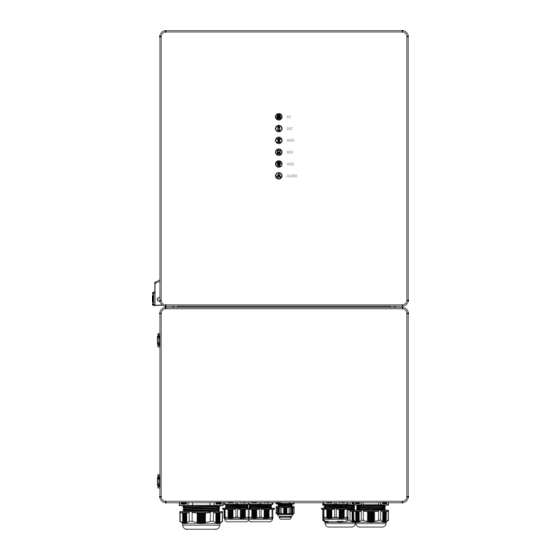
Product Introduction 2.2 Product Appearance 2.2.1 ESS Inverter 240.0 420.0 Height(mm) Width(mm) Depth(mm) LED Indicators PV BAT GRID EPS(BACKUP) COM ALARM LED Details The External View of ESS Inverter ESS Inverter User Manual... - Page 10 Product Introduction PV Switch 2. Toggle Latch ( for opening/closing the junction box cover) 3. ON/OFF Button The Left View of ESS Inverter Battery Connect Terminals 2. PV Input Terminals 3. COM1/2/3 Ports (RS485, BMS, DRM, CT, DRY, RSD, PARA) 4.
-
Page 11: Installation
Installation Installation 3.1 Packing List After unpacking, please check the following packing list carefully for any damage or missing parts. If any damage or missing parts occurs, contact the supplier for help. Number Quantity Description Inverter Mounting bracket File package Meter (Optional) M6 Expansion screws M6 Security screw... -
Page 12: Selecting The Mounting Location
Installation 3.2 Selecting the Mounting Location 3.2.1 Installation Environment Requirements a. The storage inverter protection class is IP65 and can be mounted indoors or outdoors. b. The mounting location must be inaccessible to unrelated personnel since the enclosure and heat sinks are extremely hot during operation. - Page 13 Installation 3.2.2 Mounting Requirements Mount the inverter vertically or tilted backward by max 15°. The device can not be installed with a wrong mode and the connection area must point downward. ≤15° Horizontal Upright Lean back ≤15° Upside-down 3.2.3 Installation Space Requirements To ensure the inverter normally and easy to operate, there are requirements on available spaces of the inverter, e.g.
-
Page 14: Mounting
Installation 3.3 Mounting Before mounting the inverter, you have to prepare expansion screws and a security screw. ∅16 Step 1. Install the mounting bracket 246.6 1. Use a level ruler to mark the position of the 3 holes on the wall. Refer to Figure a. And drill 3 holes, 16mm in 110.6 diameter and 55mm in deep. -
Page 15: Electrical Connection
Electrical Connection 4. Electrical Connection This chapter shows the detailed connections of ESS inverter. The following illustration only uses the hybrid inverter as an example. ESS inverter system connection diagram: Non-parallel connection mode Split phase (120/240Vac) connection diagram (US) PARA METER BMS RS485 L�... - Page 16 Electrical Connection Split Phase parallel connection mode-Scheme A (N=2) Turn this switch to “ON”. PARA ① No.2 Inverter PARA Breaker METER BMS RS485 RS485 L� GEN L� L� GRID L� L� BACKUP L� METER PV Array ① PARA No.1 Inverter METER BMS RS485 L�...
- Page 17 Electrical Connection Note: 1. PV related contents are N/A for AC Couple inverter. 2. BMS communication connection is only for lithium battery. 3. It is necessary to turn the matched resistance switch of No. 1 inverter and No. 2 inverter to “ON” in parallel connection mode.
- Page 18 Electrical Connection Split Phase parallel connection mode-Scheme B (N>2) Turn this switch to “ON”. PARA ① No.N Inverter (N>2) PARA Breaker RS485 METER BMS RS485 L� GEN L� L� GRID L� L� BACKUP L� METER PV Array ① PARA No.2 Inverter METER BMS RS485 L�...
- Page 19 Electrical Connection Note: 1. PV related contents are N/A for AC Couple inverter. 2. BMS communication connection is only for lithium battery. 3. It is necessary to additionally purchase suitable CT and meter according to the specific requirements in parallel connection mode-Scheme B. 4.
-
Page 20: Grounding
Electrical Connection 4.1 Grounding A protective earth (PE) terminal is equipped at the side of the inverter. Please be sure to connect this PE terminal to the PE bar for reliable grounding. AWG 2 or 4 yellow green lines are recommended. Grounding Terminal The bottom view... -
Page 21: Meter/Ct Connection
Electrical Connection Meter/CT Connection You can monitor usage with a meter or a CT. 4.2.1 Meter Connection This section is applicable to non-parallel connection mode only. inverter supports the meter CHINT-DTSU666 meter by default. The meter is optional. Inverter Grid Side Side Before connecting to Grid, please install a separate AC breaker (≥70A;... - Page 22 Electrical Connection 4.2.2 CT Connection Before connecting to Grid, please install a separate AC breaker (≥70A; not equipped) between CT and Grid. This will ensure the inverter can be safely disconnected during maintenance. The connection diagram of power cable of CT is shown in the figure below: Flow from grid to inverter Normal Load...
-
Page 23: Communication Connection
Electrical Connection Communication Connection There are communication interfaces in the communication port on the bottom of the inverter as show below: PARA RS485 METER PARA METER BMS RS485 L� GEN L� L� GRID L� L� BACKUP L� GPRS/WIFI/LAN Interface Descriptions 4-Pins interface for parallel communication PARA A matched resistance switch for parallel communication... - Page 24 Electrical Connection 4.3.1 BMS Connection (Only for Lithium Battery) RJ45 Terminal Configuration of Battery Communication (BMS) Pin 12345678 Function RS485_ A RS485_B CAN_H Description Function CAN_L Description This manual describes the cable sequence of the inverter. For details about the cable sequence of the battery, see the manual of the battery you used.
- Page 25 Electrical Connection 4.3.2 Connection Meter RJ45 Terminal Configuration of Meter Communication Pin 12345678 Function RS485_ A RS485_ B CT1+ CT1- Description Meter cable connection overview Meter Inverter Pin24 Pin3(RS485_A ) Pin25 Pin4(RS485_B ) Pin3 Pin4 ESS Inverter User Manual...
- Page 26 Electrical Connection Connect meter. Refer to the following steps: a. Make the RJ45 terminal according to above function description of each Pin definition. RJ45 terminals Meter cable Inverter side Meter b. Lead the meter communication cable through the gland. And insert the RJ45 terminals into corresponding ports.
- Page 27 Electrical Connection Connect CT. Refer to the following steps: a. Make the RJ45 terminal according to above function description of each Pin definition. RJ45 terminals CT cable Inverter side b. Lead the CT cable through the gland. And insert the RJ45 terminals into corresponding ports. PARA PARA METER BMS...
- Page 28 Electrical Connection 4.3.5 Parallel Communication Connection 4-Pin Terminal Configuration of parallel Communication Function GND_S PARA_SYNC CAN_L CAN_H Description Parallel communication cable connection overview No. 1 Inverter No. 2 Inverter No. N Inverter PARA PARA PARA ① BMS RS485 BMS RS485 RS485 METER METER...
- Page 29 Electrical Connection Refer to the following steps: a. Make the 4-Pin terminal according to above function description of each Pin definition. terminal 4-Pin Parallel communication cable Another inverter Inverter side side b. Lead the Parallel communication cable through the gland. And insert the 4-Pin terminal into corresponding ports.
- Page 30 Electrical Connection 4.3.6 NTC/RMO/DRY Connection(s) 9-Pin Terminal Configuration of Auxiliary Communication Function Description GEN Control Pin 123456789 GEN Control NC1 (Normal Close) NC2 (Normal Close) NC2 (Normal Close) REMO OFF GND S(NTC BAT) NTC BAT+ Refer to the following steps: a.
- Page 31 Electrical Connection 4.3.7 RSD Connection(s) 4-Pins Terminal Configuration of RSD Communication Function +12V Emergency Stop Signal Button Description Emergency Stop Signal: PARA PARA METER BMS RS485 L� GEN L� L� GRID L� L� BACKUP L� RS485 METER Normally Open Rapid Shutdown Signal Button Refer to the following steps: a.
- Page 32 Electrical Connection 4.3.8 GPRS/WIFI/LAN Module Connection (Optional) For details, please refer to the corresponding Module Installation Guide in the packing. The appearance of modules may be slightly different. The figure shown here is only for illustration. Loosen two screws Insert GPRS/WiFi/LAN module into the port,and ensure that and move the cover.
-
Page 33: System Operation
System Operation System Operation 5.1 Inverter Working Mode The inverter supports several different working modes. 5.1.1 Self Used Mode Go to the "Hybrid work mode" menu, and select the "Self used mode" working mode. Under Self Used mode, the priority of PV energy will be Load > Battery > Grid, that means the energy produced by PV gives priority to local loads, excess energy is used for charging the battery, and the remaining energy is fed into the grid. - Page 34 System Operation BACKUP is the sequence of load consumption. 1 2 3 c) No PV Input The inverter will first discharge the battery energy for home load consuming when no PV input( such as in the evening or some cloudy or rainy days). If the demand is not met then will consume the grid energy.
- Page 35 System Operation a) Wealthy PV Energy When PV energy is wealthy, the PV energy will be first consumed by loads, if there is excess PV power, then the excessive power will be fed into grid. If there is still PV energy rested after load consuming and grid feeding, then the rested PV power will be used to charge the battery.
- Page 36 System Operation c) No PV Input The inverter will first discharge the battery energy for home load consuming when no PV input ( such as in the evening or some cloudy or rainy days). If the demand is not met then will consume the grid energy.
- Page 37 System Operation 5.1.4 Back-up Mode Go to the "Hybrid work mode" menu, and select the "Back-up Mode" working mode. Under this mode, the priority of PV energy will be Battery > Load > Grid. This mode aims at charging the battery quickly, and at the same time, you can choose whether to allow AC to charge the battery.
- Page 38 System Operation Allow AC charging In this situation, the battery can be charged both with PV and AC. a) Wealthy PV power When PV energy is wealthy, PV charges the battery first, then meets the load, and the rest is fed into the grid.
- Page 39 System Operation 5.1.5 Off Grid Mode When the power grid is cut off, the system automatically switches to Off Grid mode. Under off-grid mode, only critical loads are supplied to ensure that important loads continue to work without power failure. Under this mode, the inverter can’t work without the battery.
- Page 40 System Operation b) Limited PV power When PV energy is limited, BACKUP loads are first powered by PV and then supplemented by battery. BACKUP is the sequence of BACKUP load consumption. Under this mode, please complete the output voltage and frequency settings.
-
Page 41: Startup/Shutdown Procedure
System Operation Startup/Shutdown Procedure 5.2.1 Startup Procedure Check and confirm that the installation is secure and strong enough and that the system grounding is OK. Then confirm the connections of AC, battery, PV etc. are correct. Confirm the parameters and configurations conform to relevant requirements. AC Frequency 50/60Hz PV Voltage... -
Page 42: Commissioning
Commissioning 6. Commissioning It is necessary to make a complete commissioning of the inverter system. This will essentially protect the system from fire, electric shock or other damages or injuries. 6.1 Inspection Before commissioning, the operator or installer (qualified personnel) must inspect the system carefully and make sure: 1) The system is firmly and correctly installed by following the contents and notifications of this manual, and there are enough spaces for operation, maintenance and ventilation. -
Page 43: User Interface
User Interface 7. User Interface 7.1 LED This section describes the LED panel. LED indicator includes PV, BAT, GRID, EPS(BACKUP), COM, ALARM indicators. It includes the explanation of indicator states and summary of indicator states under the running state of the machine. LED Indicator Status Description PV input is normal. - Page 44 User Interface ALARM Grid Details Code Details PV normal PV normal ● ◎ ◎ ◎ ◎ ○ No PV No PV ○ ◎ ◎ ◎ ◎ ○ PV over voltage PV over voltage PV under voltage PV under voltage PV irradiation weak PV irradiation weak ★...
- Page 45 User Interface ALARM Grid Details Code WLAN/RS485/DB9/BLE/USB ◎ ◎ ◎ ◎ ● ◎ RS485/DB9/BLE/USB Inverter over temperature Inverter over temperature Fan abnormal Fan abnormal Inverter in power limit state Inverter in power limit state ◎ ◎ ◎ ◎ ◎ ★ Data logger lost Data logger lost Meter lost...
-
Page 46: App Setting Guide
User Interface 7.2 App Setting Guide 7.2.1 Download App Scan the QR code on the inverter to download the APP. Download the APP from the App Store or Google Play. The APP should access some permissions such as the device’s location. You need to grant all access rights in all pop-up windows when installing the APP or setting your phone. - Page 47 User Interface 7.2.3 Local Setting Access Permission Before using the local setting, the APP should access some permissions. ( You can allow them when you install the APP or grant permissions in your own phone setting. ) When the APP asks for permission, please click Allow.
- Page 48 User Interface Quick Setting 1. Connect to the router. Step 1 Go to Quick Setting page. Step 2 Click each item to enter the information, then click Next. XXXXXXXX XXXXXXXX 19.1kWh 494kWh E-Today E-Total Step1 Set parameters for the inverter to connect Self used mode to the router.
- Page 49 User Interface 3. Set parameters of power limit XXXXXXXX Step 1 Click each item to enter the parameters of power limit. Step 2 Click Next. Step 3 Click Previous back to the previous page. Step3 Set parameters for the inverter to connect to the power limit.
- Page 50 User Interface Chart Under this menu, you can check the relevant data curve of energy (including Daily, Monthly and Annually). 1. Query(Daily) Data Go to Chart > page. It will show the Daily Production or Consumption Curve in this page. You can swipe the screen left and right to switch the graph.
- Page 51 User Interface Different color curves represent energy data of different XXXXXXXX icons. Click the icon to show and hide the corresponding curve of the corresponding content. Click the curves to display the specific data. You can also press the date such as “2022-03-24” in the figure to choose the day which you want to check.
- Page 52 User Interface Local Setting Homepage This page shows the basic information of inverter. Click to display the warning message. XXXXXXXX XXXXXXXX 19.1kWh 494kWh 19.1kWh 494kWh E-Today E-Total E-Today E-Total Self used mode Self used mode 2.71kW 405W 2.71kW 405W 2.21kW 0.00W 60.0W 2.21kW...
- Page 53 User Interface XXXXXXXX Maintenance 19.1kWh 494kWh E-Today E-Total Go to Console page. And click Maintenance Self used mode 2.71kW 405W 2.21kW 0.00W 60.0W Production: 19.1kWh 53.0% 47.0% 10.1kWh Consumed directly: To Grid: 8.97kWh Consumption: 9.87kWh 76.0% 24.0% 7.50kWh PV Supply directly: From Grid:2.37kWh Basic...
- Page 54 User Interface In this page, you can view the basic information like some version information, do some maintaining operations like turn off/on the inverter and manage data. �K US ESS Inverter User Manual...
- Page 55 User Interface Console Access Management Go to Console > Access Management page. In this page, you can switch the login permission. ESS Inverter User Manual...
- Page 56 User Interface Communication Setting Go to Console > Communication Setting page. In this page, you can set or change the parameters of communication settings: Basic Setting, RS485 Setting and Ethernet Setting. ESS Inverter User Manual...
- Page 57 User Interface Grid Parameters Go to Console > Grid Parameters page. In this page, you can set or change the parameters of Grid side, as shown in the figure. Feature Parameters Go to Console > Feature Parameters page. In this page, you can set or change the feature parameters, as shown in the figure.
- Page 58 User Interface Reactive Power Control Go to Console > Reactive Power Control page. In this page, you can set or change the Reactive Power Control parameters. Other Setting Go to Console > Other Setting page. In this page, you can set other setting parameters. Enable Buzzer On to open...
- Page 59 User Interface Hybrid Setting Go to Console > Hybrid Setting page. In this page, you can set Hybrid Setting parameters. XXXXXXXX ESS Inverter User Manual...
-
Page 60: Maintenance
Maintenance 8. Maintenance Before maintaining and commissioning inverter and its peripheral distribution CAUTION unit, switch off all the charged terminals of the inverter and wait at least 10 minutes after the inverter is powered off. 8.1 Routine Maintenance Maintenance Items Check Content Maintain Content Interval... -
Page 61: Inverter Troubleshooting
Maintenance 8.2 Inverter Troubleshooting When the inverter has an exception, its basic common warning and exception handing methods are shown below. Code Alarm Information Suggestions A� Grid over voltage �. If the alarm occurs occasionally, possibly the power grid voltage is abnormal for a short time, and no action is required. A�... - Page 62 Maintenance �. If the alarm occurs occasionally, possibly the power grid voltage is abnormal for a short time, and no action is required. C� Inverter over dc-bias �. If the alarm occurs repeatedly, and the inverter fails to generate power, current contact the customer service center.
- Page 63 Maintenance �. If the alarm occurs occasionally, the inverter can be automatically recovered and no action is required. Internal communication �. If the alarm occurs repeatedly, the inverter cannot work properly. Pls. error contact the customer service center. �. If the alarm occurs occasionally, the inverter can be automatically recovered and no action is required.
- Page 64 Maintenance �. If the alarm occurs occasionally, the inverter can be automatically recovered and no action is required. �. Check that the battery overvoltage protection value is improperly set. D� Battery over voltage �. The battery is abnormal. �. If exclude the above, the alarm continues to occur, please contact the customer service center.
- Page 65 Maintenance 1. Check whether the communication cables between BACKUP , electricity Internal communication meter and inverter are well connected and whether the wiring is correct D� loss(E-M) 2. Check whether the communication distance is within the specification range 3. Disconnect the external communication and restart the electricity Internal communication meter and inverter.
-
Page 66: Technical Specifications
Technical Specification 9. Technical Specification 6K US 8K US Item 5K US 10K US Input (PV) Max. Input Power 7500W 9000W 12000W 15000W MPPT Range(Full load) 200V~480V 200V~480V 200V~480V 200V~480V MPPT Range 70V-540V Max. DC Voltage 600V Max. Input Current... - Page 67 Technical Specification Model 5K US 6K US 8K US 10K US Output (BackUp) Nom. Power 5000VA 6000VA 8000VA 10000VA Maximum Power ( 60s ) 8000VA 9000VA 12000VA 15000VA Apparent Power ( 10s ) 10000VA 12000VA 16000VA 20000VA Nominal Voltage 120/240V(Split phase) / 208V(2/3 phase)
- Page 68 Technical Specification 5K US 6K US 8K US 10K US Model Protection Anti-islanding protection AC over-current protection AC short-circuit protection AC over-voltage protection DC Type2 , AC Type2 Insulation detection GFCI AFCI Tigo/APS Mechanical W x H x D 420*800*240mm...
Need help?
Do you have a question about the 5K US and is the answer not in the manual?
Questions and answers