
Related Manuals for Maxlogic ML-122 Series


Summary of Contents for Maxlogic ML-122 Series
- Page 1 COMMISSIONING, OPERATING AND MAINTENANCE MANUAL MODEL: MAXLOGIC SERIES ML-122X SUB MODEL: INTELLIGENT ANALOGUE ADDRESSABLE FIRE ALARM CONTROL PANEL...
-
Page 2: Table Of Contents
1. CONTENTS: 2. LIST OF FIGURES...........................................3 3. LIST OF TABLES..........................................3 4. INTRODUCTION..........................................4 5. INSTALLATION AND COMMISSIONING STEPS................................6 6. GENERAL EXPLANATIONS......................................6 7. FUNCTIONAL EXPLANATIONS....................................8 8. INSTALLATION..........................................9 9. COMMISSIONING........................................12 10. MAIN CARD FEATURE......................................14 11. POWER SUPPLY AND CONNECTIONS..................................15 12. GENERAL DEFINITION FOR 2ND ACCESS LEVEL FUNCTIONS (USER FUNCTIONS)..................16 13. -
Page 3: List Of Figures
2. LIST OF FIGURES Figure 1 - Loop Card (SLCU) Connection..................................10 Figure 2 - MLY-1233 MLY-122X Front side..................................13 Figure 3 - MLY-1233 MLY-122X Back side..................................13 Figure 4 - MSM-3 Power Supply appearance................................14 Figure 5 - Auxilary 24V DC output....................................18 Figure 6 - Relays on panel.........................................18 Figure 7 - Sounder outputs........................................19 Figure 8 - Panel front face.........................................20 Figure 9 - Panel front face sections....................................22... -
Page 4: Introduction
4. INTRODUCTION Thanks for choose Maxlogic series intelligent analogue addressable fire alarm panel. This document includes the necessary information about Maxlogic series intelligent analogue addressable fire alarm panel installation, maintenance, and commissioning. Also the followings are available on this document. - Page 5 WARNING SIGNS Danger – Electrical shock ! Remove all power from the panel before carrying out any installation work! ESD protection While handling electronic assemblies, the necessary precautions against electrostatic discharge must be taken. Protective earth The PE conductor must be connected to the corresponding terminal at the mains supply. Commissioning A complete system check must be carried out after commissioning.
-
Page 6: Installation And Commissioning Steps
5. INSTALLATION AND COMMISSIONING STEPS At this section the remarkable steps during Maxlogic series panels’ installation and commissioning operations are listed. Consider the followings during system design • Section 14. Power Supply Load Calculation • Section 15. Battery Capacity Calculation •... - Page 7 6.2 Maxlogic panel explanations 6.2.1 MLY-0201 A type ABS front cover (ML-12XX) Used as a front cover of ML-122X series panels. 6.2.2 MLY-0207 ML-12XX Function Lock Used as a key lock. 6.2.3 MLY-1233 ML-122X (Lite) XMCU Main card It is the main card of the panel.
-
Page 8: Functional Explanations
7. FUNCTIONAL EXPLANATIONS 7.1 List of Features Expandable modular structure up to 2 loops with totally 254 address Modular structure with 2 loops capacity. Each loop has a capacity of 127 addresses. 10 action/reaction scenario can be created which are used to make 10 automation (action/reaction) scenario automation with the surroundings. -
Page 9: Installation
7.2 Specifications which are related with requirements of EN 54 The following optional specifications are provided for Maxlogic series panels: Output for fire alarm devices 7.11 Delays to outputs 7.12.1 Dependencies on more than one alarm signal (Type A dependency) 7.12.2 Dependence for more than one alarm signal (Type B dependency) - Page 10 Allen key 4 mm 8.2.1 Maxlogic panel installation procedure The mounting location must be dry, clean, accessible, and it is not sustained vibration Panel must be mounted to a flat surface where the indicators are located on eye level. Do not mount on any other cabin or close to high temperature sources.
- Page 11 8.3 Loop Card (SLCU) Installation and Connection 1. Make sure the panel is not energized during loop card connection. 2. Please make the loop card connection as shown below: Figure 1-Loop Card (SLCU) Connection 1. Installation and connection directives of the devices used in the loop should be examined. The connection of each device type to the loop may differ.
-
Page 12: Commissioning
9. COMMISSIONING 9.1 Control list before commissioning 1. Technical personnel must control the followings before commissioning: • Cable connections on the site must be controlled. • Each cable’s panel connections must be controlled. • Control there is no un-connected detector or manual call point. •... - Page 13 9.4.2 Loops commisioning 1. Turn off the panel. 2. Make sure all of the isolators on the loop are connected precisely. 3. Remove the return line of the loop line, and isolate it to connect only in going line to the panel. Check there is no contact between cables and/or any other points.
-
Page 14: Main Card Feature
10. MAIN CARD FEATURE Figure-2 and Figure-3 shows the main card of Maxlogic series panels. (MLY-1233 ML-122X (Lite) MCU Modülü) Figure-2 -MLY-1233 ML-122X Front side Figure-3 -MLY-1233 ML-122X Back side Explanations: 1. Auxilary 24V DC supplied voltage output 9. Microprocessor reset button 15. -
Page 15: Power Supply And Connections
11. POWER SUPPLY AND CONNECTIONS Figure-4 shows the power supply which is used at panel. (MSM-3 Power Supply) Hata Ledi MSM3 POWER SUPPLY AKÜ ÇIKIŞ 24V DC 24V DC Figure 4-MSM-3 Power Supply appearance Definitions: 1. 27V AC 50 Hz Input 2. -
Page 16: General Definition For 2Nd Access Level Functions (User Functions)
12. GENERAL DEFINITION FOR 2ND ACCESS LEVEL FUNCTIONS (USER FUNCTIONS) At this section there are general explanations related with the functions which are accessible for final user 12.1 Accessing device information Device’s type, address, zone, location information, analogue value, disable condition information can be monitored. This information are just for information oriented, and the information cannot be changed. -
Page 17: Power Supply Load Calculation
14. POWER SUPPLY LOAD CALCULATION The current which is received from the power supply for Maxlogic fire alarm panel shall not exceed 3 A. the maximum load value for this current value is calculated as shown below. -
Page 18: Battery Capacity Calculation
15. BATTERY CAPACITY CALCULATION This section contains the time calculations depend on the used load condition when main network’s supplied power is cut out for fault and alarm condition. 1. Ipanel_fault: It is the maximum measured current value on fault condition when there is no main network supply. During this value is measured, sounder outputs and 24 output does not connected. -
Page 19: Panel Input/Output Connections
16. PANEL INPUT/OUTPUT CONNECTIONS 16.1 Auxilary 24V output 24V DC 500mA 24V DC Figure 5-Auxilary 24V DC output 24V DC 500 mA external power supply output is available. Exceeding this level may cause panels fault messages. This output can be used for external devices’ supplied power line. During power cut, 24V DC supplied voltage output is supplied from battery until battery in run out. - Page 20 16.3 Sounder outputs Figure 7-Sounder outputs There are 2 pcs. of 24V DC 500mA sounder output on the panel. Normally, there is a 16V DC negative voltage on the sounder outputs to control sounder line’s short/open circuit conditions. It is driven 24V DC voltage during fire alarm. Dropping high voltages from these outputs may cause fault messages.
-
Page 21: Loop
17. LOOP Short circuit isolators must be used to prevent the effect of the short circuit which may occurred on the loop line, disabled the whole loop. 17.1 Loop isolators Short circuit isolators have been used to prevent detectors and other devices on the loop which are not affected short circuit during short circuit condition. -
Page 22: System Fault Condition
After controlling the alarmed location “Alarm” button on the fire alarm panel must be pushed. The silenced sounders resounds again when this button have been pushed. If there the fire alarm is wrong, the cause of the wrong alarm must be cleared and system is passed through to the normal operating mode by pushing “Reset”... -
Page 23: Nd Access Level (User) Controls And Functions
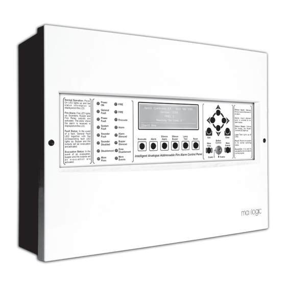
20. 2nd ACCESS LEVEL (USER) CONTROLS AND FUNCTIONS Fire alarm panel’s front face will be examined at 5 sections; Figure 9 - Panel front face sections Shows there is a fire alarm on the system. Shows the power is on. Shows there is a fault at system. - Page 24 This button is used to display 1 on the related This button is used to display 4 on the related menu step or it is used as up arrow key. menu step or it is used as left arrow key This button is used to display 2 on the related menu step or it is used as right arrow key.
- Page 25 20.1 How to display feature/analogue measurement result of devices in loops? 1. [Button Control] must be switched to “Enable” position. 2. Press [Enter] to view menu. A C C E S S L E V E L 2 M E N U >...
- Page 26 L O O P S T A T U S E N A B L E - - - - - - - - - - - - - - - - - - - - - - - - - - - - - - - - - - - - - - - - - - - - - - [ U p / D o w n ] : S c r o l l [ R i g h t ] : S e l e c t...
- Page 27 C H A N G E S T A T U S E N A B L E ( P r e s s [ E n t e r / R i g h t ] f o r d i s a b l e ) - - - - - - - - - - - - - - - - - - - - - - - - - - - - - - - - - - - - - - - - - - - - - - [ R i g h t / E n t e r ] : A c c e p t 20.4 How to disable and enable any device?
- Page 28 C H A N G E S T A T U S E n a b l e ( P r e s s [ E n t e r / R i g h t ] f o r d i s a b l e ) - - - - - - - - - - - - - - - - - - - - - - - - - - - - - - - - - - - - - - - - - - - - - - [ R i g h t / E n t e r ] : A c c e p t 20.5 How to disable and enable sounders?
- Page 29 20.6 How to make control panel time settings? 1. [Button Control] must be switched to “Enable” position. 2. Press [Enter] to view menu. 3. Press [3-Down] button twice in the new menu to select “Set System Time” option. Confirm this selection by pressing [Enter] button.
- Page 30 F i r e A l a r m C o u n t e r T o t a l F i r e A l a r m s : - - - - - - - - - - - - - - - - - - - - - - - - - - - - - - - - - - - - - - - - - - - - - - [ E x i t / L e f t ] : B a c k 20.8 How to activate / deactivate output delays? [Program enable switch] must be in the “Enable”...
- Page 31 T e s t > L o o p T e s t Z o n e T e s t D e v i c e T e s t - - - - - - - - - - - - - - - - - - - - - - - - - - - - - - - - - - - - - - - - - - - - - - [ U p / D o w n ] : S c r o l l [ R i g h t ] : S e l e c t...
- Page 32 T e s t > L o o p T e s t Z o n e T e s t D e v i c e T e s t - - - - - - - - - - - - - - - - - - - - - - - - - - - - - - - - - - - - - - - - - - - - - - [ U p / D o w n ] : S c r o l l [ R i g h t ] : S e l e c t...
- Page 33 T e s t > L o o p T e s t Z o n e T e s t D e v i c e T e s t - - - - - - - - - - - - - - - - - - - - - - - - - - - - - - - - - - - - - - - - - - - - - - [ U p / D o w n ] : S c r o l l [ R i g h t ] : S e l e c t...
-
Page 34: Rd Access Level (Engineering) Controls And Functions
M O R E E V E N T S > F i r e s : 2 E v a c u a t e s : 0 F a u l t s : 0 P r e A l a r m s : 0 - - - - - - - - - - - - - - - - - - - - - - - - - - - - - - - - - - - - - - - - - - - - - - [ U p / D o w n ] : S c r o l l... - Page 35 P A S S W O R D E N T R Y U s e d i r e c t i o n b u t t o n s 1 3 4 * - - - - - - - - - - - - - - - - - - - - - - - - - - - - - - - - - - - - - - - - - - - - - - [ E x i t ] : C a n c e l [ E n t e r ] : A c c e p t Exit from access level 3 menu occurs if any button is not pressed while 20 seconds in access level 3.
- Page 36 R e s o u n d i n g C o n d i t i o n > N e v e r R e s o u n d R e s o u n d i n g E v e n t F r o m D i f ,...
- Page 37 P a n e l C o n f i g u r a t i o n R e s e t t i n g S c e n a r i o T r i g g e r e d E v e n t s S c e n a r i o A c t i v a t i o n...
- Page 38 21.7 How to display time values used for Dar / Night Mode? 1. 1-2-3-4 steps must be realized in article 21.1. 2. [Enter] button must be pressed while the cursor is on “Panel Configuration” option. 3. “Panel Time Settings” must be selected by pressing [3-Down] button once. P a n e l C o n f i g u r a t i o n P a n e l...
- Page 39 21.9 How to display event logs in categories? 1. 1-2-3-4 steps must be realized in article 21.1. 2. “Event Logs” must be selected by pressing [3-Down] button once. A c c e s s L e v e l P a n e l C o n f i g u r a t i o n >...
- Page 40 21.10 How to display event logs in order? 1. 1-2-3-4 steps must be realized in article 21.1. 2. “Event Logs” must be selected by pressing [3-Down] button once. A c c e s s L e v e l P a n e l C o n f i g u r a t i o n >...
- Page 41 E v e n t L o g s V i e w l i s t P r i n t C a t e g o r y P r i n t l i s t > C l e a r E v e n t L o g s...
- Page 42 O l a y D ü z e n l e K a y ı p c i h a z H a t a Y e n i c i h a z H a t a - - - - - - - - - - - - - - - - - - - - - - - - - - - - - - - - - - - - - - - - - - - - - - [ Y u k a r ı...
- Page 43 21.14 How to update software version of SLCU? 1. “Bootloader Control” software program must be run. 2. Select S08 file for uploading to SLCU after opening S08 file by clicking on “Open S08 File” button through Bootloader Control software program. 3.
- Page 44 10. The updated version data will appear at the end of this process. Press [Exit] button to quit. S L C U A p p , S o f t w a r e L c u 1 - B . V . [ 1 . 0 . 0 ] / A p p .
- Page 45 C o n t a m i n a t i o n C o n t r o l > A u t o m a t i c C o n t r o l M a n u a l C o n t r o l - - - - - - - - - - - - - - - - - - - - - - - - - - - - - - - - - - - - - - - - - - - - - - [ E x i t ] :...
- Page 46 C o n t a m i n a t i o n C o n t r o l > A u t o m a t i c C o n t r o l M a n u a l C o n t r o l - - - - - - - - - - - - - - - - - - - - - - - - - - - - - - - - - - - - - - - - - - - - - - [ E x i t ] :...
- Page 47 C o n t a m i n a t i o n C o n t r o l > G e n e r a l ( M a n u a l ) L o o p 2 : 2 D e v i c e s ( M a n u a l )
- Page 48 C o n t a m i n a t i o n C o n t r o l M G 9 1 0 0 O p t . S m o k e D e t . Z o n e : 1 P : 0 L : 2 A : 7 5...
- Page 49 C o n t a m i n a t i o n C o n t r o l M e a s u r i n g c o n t a m i n a t i o n s t a t u s - - - - - - - - - - - - - - - - - - - - - - - - - - - - - - - - - - - - - - - - - - - - - - [ E x i t / L e f t ] : B a c k...
- Page 50 M a n u a l C o n t a m i n a t i o n C o n t r o l c o u n t : 8 I n t e r r o g a t i o n - - - - - - - - - - - - - - - - - - - - - - - - - - - - - - - - - - - - - - - - - - - - - - [ R i g h t / E n t e r ] : A c c e p t [ E x i t / L e f t ] : B a c k...
- Page 51 C o n t a m i n a t i o n C o n t r o l A u t o m a t i c C o n t r o l > M a n u a l C o n t r o l - - - - - - - - - - - - - - - - - - - - - - - - - - - - - - - - - - - - - - - - - - - - - - [ E x i t ] :...
- Page 52 S e l e c t C o n f i g T y p e R e – I n i t i a t e S y s t e m P r o g r a m U s e V a l i d D a t a...
- Page 53 21.22 How to download site specific data from control panel? 1. Connection between control panel and computer must be established. 2. Control panel must be on normal operating condition mode. 3. Select File>Download from Panel through Loop Manager+ Lite software program. 4.Select the com port where the communication will be made and press the start button.
- Page 54 21.23 How to upload site specific data to control panel? 1. [Program Enable Switch] must be enabled in order to send data. There should not be any fire event. 2. Connection between computer and control panel must be established. 3. Firstly, select the panel. Then, select Operations>Upload to Panel through Loop Manager+ Lite software program. 4.
- Page 55 21.24 How to set output delay? A delay time will be assigned to sounder output 1 of control panel as an example: 1. Run Loop Manager+ Lite software program. 2. Double click on Sounder 1 and display Device Settings window 3.
- Page 56 21.25 How to change data of devices in loop? 1. Open device settings window by double clicking on the requested device that will be changed the data. 2. Features may differ depending on device type. All requested changes must be made and confirmed. 3.
- Page 57 21.26 How to set dependency (pre-alarm feature) for more than one alarm signal in type A and B? 1. Zone settings window must be open for the zone which will be effected by more than one alarm signal in type A or type B. 2.
- Page 58 21.27 How to set dependency for more than one alarm signal in type C (Creating scenario)? 1. The "Scenarios" menu must be selected from the operations menu. 2. Select control panel for which it is requested to create a scenario, right click on this control panel and select “New Scenario”. 3.
- Page 59 4. All requested settings must be made, confirmed and uploaded to the control panel. 21.28 How to change control panel settings? 1. “Features” window must be open by right clicking on requested control panel. KK-641.091 Rev.No:1 17.11.21 ML-122X User Manual Page 59/72...
- Page 60 2. “Save” all requested changes. All confirmed changes must be uploaded to the control panel. KK-641.091 Rev.No:1 17.11.21 ML-122X User Manual Page 60/72...
-
Page 61: Operations On The Periodic Maintenance
22. OPERATIONS ON THE PERIODIC MAINTENANCE • Bakım onarım konusunda; ürünü toza, neme, darbeye, düşmeye, suya karşı korumalısınız. • Herhangi bir arıza söz konusu olduğunda veya ürünün bakımının yapılması gerektiğinde bakım ve onarım, mutlaka üretici firmanın yetkili servisi tarafından veya üretici firmanın yetki verdiği teknisyenler tarafından yapılmalıdır. Periyodik bakım gerektirmesi durumunda, periyodik bakımın yapılacağı... -
Page 62: Information About Usage Errors
The periodic control of the devices of fire detection system includes the followings; 1. If periodic maintenance operations have been generating at the first time, each devices’ address information’s must be controlled, 2. If any of the line’s element number have been changed between the time of two maintenance period, related line’s devices’ address information’s must be controlled, 3. -
Page 63: Annex-A - Ml-122X Series Panel Structure
KK-641.091 Rev.No:1 17.11.21 ML-122X User Manual Page 63/72... -
Page 64: Annex-B Panel Dimensions And Mounting Holes
ANNEX-B PANEL DIMENSIONS AND MOUNTING HOLES 231,0 155,5 155,5 KK-641.091 Rev.No:1 17.11.21 ML-122X User Manual Page 64/72... -
Page 65: Annex - 2Nd Access Level (User) Menu
ANNEX - 2nd Access Level (User) Menu 2nd ACCESS LEVEL MENU Loop 1: XXX Device Displayed Device Features DEVICES View Devices By Loop Loop 2: XXX Device Displayed Device Features Loop 1: XXX Device: Loop 1: -Condition- (Condition: Disable type: Untimed DISABLEMENT Disable Loop Enable / Disable) -
Page 66: Annex - 3Rd Access Level (Engineering) Menu
ANNEX - 2nd Access Level (User) Menu Sounder1: -Condition- (Condition: Disable Sounder All Sounders: Condition Disable type: Untimed Enable / Disable) Edit System Time View System Time Set System Time (Day/Month/Year) (Day/Month/Year) Day:Time Monday:14:42 Fire Alarm Counter Total Fire Alarms:x Delay Configuration Delays: Enable / Disable Loop test - Condition:... - Page 67 ANNEX - 3rd Access Level (Engineering) Menu 3rd ACCESS Password Entering Screen LEVEL MENU (Use direction arrow keys.) Panel General Supplier Name Panel Configuration Settings Panel Text System Operation Mode Level 3 Password Zonee Starting LED number Zone LED count Resounding condition Herhangi bir bölgeden alarm gelirse...
- Page 68 ANNEX - 3rd Access Level (Engineering) Menu Panel Time Settings Panel version XMCU: 1.0.XX-0.0.0 informations SLCU: 1.0.XX-0.0.0 NCU: 1.0.XX-0.0.0 PCUÇ 1.0.XX-0.0.0 Network status Fire: x View by category Event Logs Evacuations:x Faults: x Pre-alarms: x View by list Fire: x Print by category Evacuations:x Faults: x...
- Page 69 ANNEX - 3rd Access Level (Engineering) Menu Measuring Contamination control Interrogation count:x General Automatic control contamination status Interrogation Measure Manual control count:x List results Print results Measuring Loop:1 Automatic control Interrogation count:x contamination status Interrogation Measure Manual control count:x List resul Print results Measuring Loop:2...
-
Page 70: Annex - Explanations Of The Terms
ANNEX - Explanations of the Terms Ampere - current. Alternative current Ampere / time - battery capacity Direct current Electro-magnetic compatibility End line resistance Input / output Liquid cristal display Light-emitting diode Personal computer Electronic circuit board Voltage Firmware Software for the defined functions ANNEX - Abbreviations SMPS Switched mode power supply... - Page 71 Battery Definitions Battery 2 pcs. of - Z12-7 Sealed battery 12V Battery capacity Max. 7Ah Battery charge voltage 27,6V DC Battery charge current Max. 1100mA Loop Output Definitions Maksimum akım Her çevrim için 180mA Protection 500mA short circuit protection Communication İletim Tipi Half-duplex, 2 wired serial synchronize digital communication, time-based sending, current receiving...
-
Page 72: Models
24 - MODELS Product Code Product Description ML-1221 Maxlogic Intellegent Addressable Fire Alarm Control Panel, 1 Loop 127 Addresses ML-1222 Maxlogic Intellegent Addressable Fire Alarm Control Panel, 2 Loop 254 Addresses 1922 Mavili Elektronik Ticaret ve Sanayi A.Ş. Şerifali Mahallesi, Kutup Sokak No:27/1-2-4 Ümraniye TR-34775 İSTANBUL...
Need help?
Do you have a question about the ML-122 Series and is the answer not in the manual?
Questions and answers