Sign In
Upload
Download
Table of Contents
Contents
Add to my manuals
Delete from my manuals
Share
URL of this page:
HTML Link:
Bookmark this page
Add
Manual will be automatically added to "My Manuals"
Print this page
×
Bookmark added
×
Added to my manuals
Manuals
Brands
Maxlogic Manuals
Control Panel
ML-123X Series
Operating, maintenance and commissioning
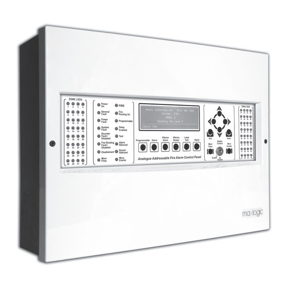
Maxlogic ML-123X Series Operating, Maintenance And Commissioning
Intelligent analogue addressable fire alarm control panel
Hide thumbs
1
2
Table Of Contents
3
4
5
6
7
8
9
10
11
12
13
14
15
16
17
18
19
20
21
22
23
24
25
26
27
28
29
30
31
32
33
34
35
36
37
38
39
40
41
42
43
44
45
46
47
48
49
50
51
52
53
54
55
56
57
58
59
60
61
62
63
64
65
66
67
68
69
70
71
72
73
74
75
page
of
75
Go
/
75
Contents
Table of Contents
Bookmarks
Table of Contents
Table of Contents
LIST of FIGURES Figure 1-Loop Card (SLCU) Connection
Loop Voltage Drop Calculation
Panel Events
Fire Condition
Fault Condition
System Fault Condition
Corruptions of Special Data on Site
System Faults Based on Interface Errors
Service Personals Needs to Do
Nd ACCESS LEVEL (USER) CONTROLS and FUNCTIONS
How to Display Feature/Analogue Measurement Result of Devices in Loops
How to Disable and Enable Loops
How to Disable and Enable a Zone
How to Disable and Enable any Device
How to Disable and Enable Sounders
How to Disable and Enable Fire Routing Output
How to Make Control Panel Time Settings
How to Display Total Fire Alarm Number
How to Activate / Deactivate Output Delays
How to Test a Loop
How to Test a Zone
How to Test a Device
How the Suppressed Fire Events, Fault Events and Other Warnings Are Viewed
How to View Suppressed Disablement Events
Rd ACCESS LEVEL (ENGINEERING) CONTROLS and FUNCTIONS
How to Reach Access Level 3, Which Is Engineering Level
How to Display General Settings of Fire Alarm Control Panel
How to Set Resounding Condition after Silencing Alarms with Silence Alarm Button
How to Set Automatic Reset Time for Test
How to Set Automatic Reset Time for more than One Alarm Signal in Type a Dependency
How to Set Automatic Reset Time for more than One Alarm Signal in Type B Dependency
How to Display Time Values Used for Dar / Night Mode
How to Display Software Version Data of Processors Used in Control Panel
How to Display Control Panels in Network
How to Display Event Logs in Categories
How to Display Event Logs in Order
How to Print Event Logs Categorically
How to Print Event Logs as Being Arranged in Time Sequence
How to Cancel Printing Event Logs Process
How to Erase Event Logs
How to Print Control Panel Settings
How to Update Software Version of SLCU
How to Enable Automatic Contamination Check for All Loops
How to Make Manual Contamination Control for All Loops
How to See Results of Manual Contamination Control for All Loops
How to Enable Automatic Contamination Control for any Loop
How to Make Manual Contamination Control for any Loop
How to Display the Results of Manual Contamination Control for any Loop
How to Apply Automatic Learning
How to Download Site Specific Data from Control Panel
How to Upload Site Specific Data to Control Panel
How to Set Output Delay
How to Alter Data of Devices in Loop
How to Set Dependency (Pre-Alarm Feature) for more than One Alarm Signal in Type a and B
How to Set Dependency for more than One Alarm Signal in Type C (Creating Scenario)
How to Assign Event to Remote Inputs
How to Modify Control Panel Settings
How to Set Control Panel Behaviors in Network
Operations on the Periodic Maintenance
Annex-A Ml-123X Series Panel Structure
Annex-B Ml-124X Series Panel Structure
ANNEX - 2Nd Access Level (User) Menu
ANNEX - 3Rd Access Level (Engineering) Menu
ANNEX - Explanations of the Terms
ANNEX - Abbreviations
ANNEX - Mechanic and Outside Definitions
ANNEX - Input / Output Definitions
Advertisement
Quick Links
1
Table of Contents
2
List of Figures Figure 1-Loop Card (Slcu) Connection
3
Loop Voltage Drop Calculation
4
Panel Events
5
Fault Condition
Download this manual
COMMISSIONING, OPERATING AND MAINTENANCE MANUAL
MODEL: MAXLOGIC SERIES
SUB MODEL: INTELLIGENT ANALOGUE
ADDRESSABLE FIRE ALARM CONTROL PANEL
Table of
Contents
Previous
Page
Next
Page
1
2
3
4
5
Advertisement
Table of Contents
Need help?
Do you have a question about the ML-123X Series and is the answer not in the manual?
Ask a question
Questions and answers
Related Manuals for Maxlogic ML-123X Series
Control Panel Maxlogic ML-121X Operating And Maintenance Manual
(36 pages)
Control Panel Maxlogic ML-322 Comissioning, Operating And Maintenance Instructions
(53 pages)
Control Panel Maxlogic ML-125 Series Operating, Maintenance And Commissioning
Intelligent analogue addressable fire alarm control panel (31 pages)
Control Panel Maxlogic ML-5020 Operating, Maintenance And Commissioning
Announce/alarm matrix panel (19 pages)
Control Panel Maxlogic ML-1230.N Operating, Maintenance And Commissioning
Intelligent analogue addressable fire alarm control panel (75 pages)
Control Panel Maxlogic ML-122 Series Operating And Maintenance Manual
Intelligent analogue addressable fire alarm control panel (72 pages)
This manual is also suitable for:
Ml-124x series
Ml-124x.p series
Ml-1230.n
Ml-1231.en
Ml-1232.en
Ml-1233.en
...
Show all
Ml-1234.en
Ml-1241.p.en
Ml-1242.p.en
Ml-1243.p.en
Ml-1244.p.en
Table of Contents
Save PDF
Print
Rename the bookmark
Delete bookmark?
Delete from my manuals?
Login
Sign In
OR
Sign in with Facebook
Sign in with Google
Upload manual
Upload from disk
Upload from URL


Need help?
Do you have a question about the ML-123X Series and is the answer not in the manual?
Questions and answers