
Related Manuals for Maxlogic ML-125 Series


Summary of Contents for Maxlogic ML-125 Series
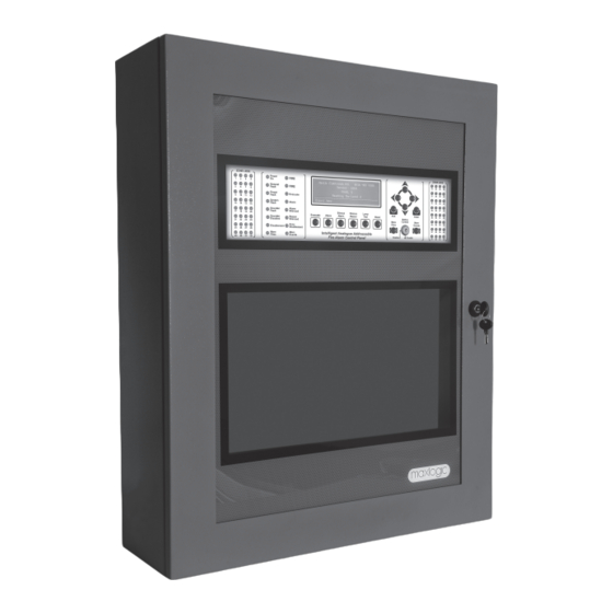
- Page 1 COMMISSIONING, OPERATING AND MAINTENANCE MANUAL MODEL: MAXLOGIC SERIES ML-125XX SUB MODEL: INTELLIGENT ANALOGUE ADDRESSABLE FIRE ALARM CONTROL PANEL...
-
Page 2: Table Of Contents
CONTENTS 1 - INTRODUCTION..................................3 2 - WARNINGS....................................3 3 - MOUNTING....................................4 4 - PANEL INPUTS..................................... 4 4.1 Mains power supply..................................4 4.2 Batteries..................................... 4 4.3 Detection Devices Inputs (Loop Lines)............................4 4.4 PC and Printer Connection................................4 4.5 Remote Control Inputs................................. 5 5 - PANEL OUTPUTS.................................. -
Page 3: Introduction
1 - INTRODUCTION Maxlogic ML-125XX series intelligent analogue addressable fire alarm control panels are provided with 0, 1, 2, 3, 4, 5, 6, 7, 8, 9, 10, 11, 12, 13, 14, 15, 16 loop options and 1000 user- defined zone capacity. Up to 127 analogue addressable devices per loop are allowed to be connected. -
Page 4: Mounting
• Should call the technicians if its necessary. • Should not repair and maintenance except for authorized people. 3 - MOUNTING The chosen mounting site of the panel must be clean, dry, not subject to shock or vibration and easily accessible. The temperature must be in between the temperature range of -5°C and +50°C. -
Page 5: Remote Control Inputs
4.5 Remote Control Inputs There are remote control inputs on the panel which are likely to control the panel remotely by the help of any remote button. One terminal of the button is connected to the desired input and other one is connected to GND. (See Annex-B, Figure-6). It should be used the cable with this code;... - Page 6 Evacuate : Used for the purpose of evacuation. It requires to be programmed by the Loop Manager Program. Pressing this button: - Buzzer sounds. - Sounders ring. - Alarm and fire relays get activated. - Fire LEDs and Evacuation LEDs illuminate. Alarm : Pressing Alarm button reactivates the sounders and relay outputs which were silenced before.
-
Page 7: Front Panel Indicators
6.2 Front Panel Indicators FIRE : Fire LEDs illuminate in two conditions; if there is a fire situation in the system or in case of pressing Evacuate button. Each one of these conditions makes the LEDs illuminate in ‘Red’ colour. Power On : Panel is energized and operates normally. -
Page 8: Panel Fuses
7 - PANEL FUSES Fuses on the panel; SLCU Fuse (FS1) is a self-resetting and activate on 0.5А current overload at the loop output line. The General fault LED illuminates and on LCD screen ‘Loop open or Short circuit’ comment is seen. Panel’s loop output becomes unusable. In each single loop card this fuse is present. Sounder 1 Self-resetting fuse (FSO3) Self-resetting and gets activated on 0.5А... -
Page 9: First Boot Of Panel
8.1. First Boot of Panel 8.1.1. Cabling: Before powering the panel, all connections should be made properly depending on the connection scheme in ANNEX-B. 8.1.2. Checking cabling: All the connected cables (sounder line, loop etc.) should be checked for short circuit, open circuit (broken line) etc. - Page 10 8.1.4.1. Re-Initiate System (Automatic Learning) Automatic learning is the operation that the panel scans and saves all devices connected to the loop lines one by one. Auto learning is activated by pressing ‘ENTER’ button. Below screen is displayed: S e l e c t C o n f i g T y p e C l e a r V a l i d D a t a ?
- Page 11 When data transfer completed, the following comment is displayed on the program; In case any communication fault occurs, the below screen appears: KK-641.008 Rev.No:10 20.04.18 ML-125XX User Manual 11/31...
-
Page 12: Booting Previously Configured Panel
In this case, the panel should be deenergized, the connection cables should be checked and all the above steps should be repeated after debugging the problem. 8.1.5. Booting panel: At the end of automatic learning or computer/panel communication, system boots in normal operation mode. On the LCD screen of the panel following comment is seen;... -
Page 13: Fire Event Message Format On Panel Lcd Screen
M a v i l i E l e k t r o n i k A . S . 0 2 1 6 4 6 6 V e r s i o n : 1 . 0 . 2 2 M L - 1 2 X X R e - i n i t i a t e d A c c e s s L e v e l 2 _ _ _ _ _ _ _ _ _ _ _ _ _ _ _ _ _ _ _ _ _ _ _ _ _ _ _ _ _ _ _ _ _ _ _ _ _ _ _ _ _ _... -
Page 14: Fault Event Message Format On Lcd Screen
10 - FAULT EVENT MESSAGE FORMAT ON LCD SCREEN On fault event, the panel displays a message in 6 lines as shown below; fault relays get activated and buzzer rings. Z o n e s A l a r m : 0 D i s . - Page 15 +ACCESS LEVEL 3: c) Access level 3: Special settings can be made from this menu. ‘Access Level 3’ option must be selected to get access to ‘Access Level 3 Menu’. “1,3,4,2” Password must be entered to Password Entry field by using direction buttons. (This password can be personalized through Loop Manager (Panel Settings - >...
- Page 16 -Global Silence: When selected as active; all outputs can be silenced by pressing ‘Silence Alarm’ button. When selected as passive; only devices, which are marked as “Yes” for “Is silenceable Output?” parameter to be accessed through Loop Manager in “Device Settings” section, can be silenced by pressing ‘Silence Alarm’ button. +Automatic Reset Delay Configuration: +Test Reset Delay: -Test Reset Delay: 6-30 sec.: This indicates the ‘TEST’...
- Page 17 -LCU 1 – B.V. (1.0.0) /A.P.P.V. (1.0.12) +Contamination Control: The system devices may be contaminated in time because of the environmental reasons. These devices can cause “FALSE ALARMS”. In order to prevent this issue, a regular maintenance must be made periodically.
-
Page 18: Networking Principles
12 - NETWORKING PRINCIPLES So that Maxlogic series fire alarm control panels can operate in network, each panel must contain 1 unit of ML-1201 Network Module. Please, see Section “15- Panel Models” which includes ML-125XX models having network module by default. ML-1201 Network Module should NOT be added for those panels which have a network module by default. -
Page 19: Connection Of Thermistor To Power Supply
SWITCH 2 - Used to set the communication speed, operation type and end of line resistor of Panel which will operate in the network. 250 Kbps 100 Kbps 50 Kbps 20 Kbps 10 Kbps End of line Resistor Communication Speed 5 Kbps Operating Type Communication... -
Page 20: Technical Specifications
Maxlogic Intelligent Analogue Addressable System Fire Alarm Control Panel, 1 Loop, 127 Address ML-1251.NPTA Maxlogic Intelligent Analogue Addressable System Fire Alarm Control Panel, 1 Loop, 127 Address, Network, Printer, Tel. PA. ML-1252 Maxlogic Intelligent Analogue Addressable System Fire Alarm Control Panel, 2 Loops, 254 Address ML-1252.NPTA... -
Page 21: Annex-A Panel Dimensions And Mounting Holes
ANNEX-A PANEL DIMENSIONS AND MOUNTING HOLES Figure 1 - Panel Dimensions KK-641.008 Rev.No:10 20.04.18 ML-125XX User Manual 21/31... - Page 22 Figure 2 - Mounting Holes KK-641.008 Rev.No:10 20.04.18 ML-125XX User Manual 22/31...
-
Page 23: Annex-B Panel Connection Scheme
ANNEX-B PANEL CONNECTION SCHEME KK-641.008 Rev.No:10 20.04.18 ML-125XX User Manual 23 /31... -
Page 24: Annex-C Panel Spare Parts
KK-641.008 Rev.No:10 20.04.18 ML-125XX User Manual 24/31... -
Page 25: Annex-D Serial Communication Cable
ANNEX-D SERIAL COMMUNICATION CABLE KK-641.008 Rev.No:10 20.04.18 ML-125XX User Manual 25/31... -
Page 26: Annex-E Scheme Of Menu Functions
ANNEX-E SCHEME OF MENU FUNCTIONS ACCESS LEVEL 2 Loop 1: XXX Device Device Data DEVICES View Devices By Loop Loop 2: XXX Device Device Data Device Data Loop XXX: XXX Device Device Data Loop 1 : Status - Loop 1: XXX Device : Disablement Type: DISABLEMENTS Disable Loop... - Page 27 Loop test - Status : Loop 1: XXX Device TEST Loop Test Enable / Disable Loop test - Status : Loop 2: XXX Device Enable / Disable Loop test - Status : Loop XX: XXX Device Enable / Disable Zone test - Status : Zone 1: XXX Device Zone Test Enable / Disable...
- Page 28 Bypassing condition Bypassing CE delays Resounding scenario Events Resettting scenario triggered events Scenario activation Programming swith usage Global silence Test Reset Automatic Reset Delay Test Reset Delay 6-30 sn Delay configuration Type A Dependency Type A Reset Delay 30-1800 sn Reset Delay Type B Type B Reset Delay 30-1800 sn...
- Page 29 Contamination Control General Automatic control Interrogation count : x Measuring contamination status Interrogation Manual control Measure count : x List results Print results Measuring contamination status Interrogation count : x Loop : 1 Automatic control Interrogation Measure Manual control count : x List results Print results Automatic control...
-
Page 30: Annex-F Network Connection Scheme
ANNEX-F NETWORK CONNECTION SCHEME 2x0.75 LIHCH FE 180 / PH 120 30/31 KK-641.008 Rev.No:10 20.04.18 ML-125XX User Manual... - Page 31 Product Code CPR No Product Code CPR No ML-1250.N 1922-CPR-0622 ML-1258.NPTA 1922-CPR-0605 ML-1250.NPTA 1922-CPR-0621 ML-1259 1922-CPR-0604 ML-1251 1922-CPR-0620 ML-1259.NPTA 1922-CPR-0603 ML-1251.NPTA 1922-CPR-0619 ML-12510 1922-CPR-0602 ML-1252 1922-CPR-0618 ML-12510.NPTA 1922-CPR-0601 ML-1252.NPTA 1922-CPR-0617 ML-12511 1922-CPR-0600 ML-1253 1922-CPR-0616 ML-12511.NPTA 1922-CPR-0599 ML-1253.NPTA 1922-CPR-0615 ML-12512 1922-CPR-0598 ML-1254 1922-CPR-0614 ML-12512.NPTA...
Need help?
Do you have a question about the ML-125 Series and is the answer not in the manual?
Questions and answers