
Related Manuals for Maxlogic ML-322


Summary of Contents for Maxlogic ML-322
- Page 1 COMMISSIONING, OPERATING AND MAINTENANCE MANUAL ML-322 MODEL: MAXLOGIC SERIES SUB MODEL: CONVENTIONAL FIRE EXTINGUISHING PANEL...
-
Page 2: Table Of Contents
16.4 Gas Activated Output ........................................30 16.5 Relays on panel ...........................................31 16.6 Signal relays on panel .......................................31 16.7 Detection zone lines ........................................32 16.8 Abort input ...........................................32 16.9 Reset input ............................................33 KK-642.041 Rev No:1 01.08.12 ML-322 Maxlogic fire extinguishing panel operating manual Page 2/53... - Page 3 Figure 19-Abort Input ..........................................32 Figure20-Reset Input ..........................................33 Figure 21-Extinguishing release input ....................................33 Figure 22-Low pressure input......................................34 Figure 23-Extinguishing condition switch input ................................34 Figure 24-Panel’s front side .........................................36 KK-642.041 Rev No:1 01.08.12 ML-322 Maxlogic fire extinguishing panel operating manual Page 3/53...
-
Page 4: List Of Tables
Figure 25-Connection between panel and extinguishing status indicator units ....................41 3. LIST OF TABLES Table-1: Classi�ications of the panel’s case types................................5 Table-2: Compatible site devices ......................................12 KK-642.041 Rev No:1 01.08.12 ML-322 Maxlogic fire extinguishing panel operating manual Page 4/53... -
Page 5: Introduction
• When required operations have been performed to alarms which have been registered after last operation day. • If disable, experiment or silence operations have been occurred and system turned back to normal operation mode. This document contains documents which are required for ML-322 series Maxlogic fire extinguishing panel’s installation, maintenance and commissioning operations. -
Page 6: Program Scenarios (If Available)
Main board that is used on ML-322 series panel s. 6.2.5 MLY-3203 Maxlogic ML-322 conv.panel.back.TR Front side Metallic Main Board Metallic mounted front side serigraphy of the main board that is used on ML-322 series panels. 6.2.6 MLY-3702 Maxlogic panel.back.ML-321 metallic RU serigraphy Metallic front side serigraphy that is used on ML-322 series panels. -
Page 7: Functional Specifications
Event logs can be received from panel and displayed by Pc software. Receiving event logs via RS-232 port. Event logs on the panel can be received from RS-232 and printed. (with PC, printer) KK-642.041 Rev No:1 01.08.12 ML-322 Maxlogic fire extinguishing panel operating manual Page 7/53... -
Page 8: Installation
Panel’s main supply line must be prepared as described on section 8.1. Electrical safety. Please be sure that the whole cables should be entered to the panel. Cable connections must be performed by authorized technical personnel. KK-642.041 Rev No:1 01.08.12 ML-322 Maxlogic fire extinguishing panel operating manual Page 8/53... -
Page 9: Commissioning
3. Panel’s zone line’s polarization must be controlled and zone line input should be connected. 4. Energized the panel, fix any of the short or open circuit condition. KK-642.041 Rev No:1 01.08.12 ML-322 Maxlogic fire extinguishing panel operating manual Page 9/53... -
Page 10: Specifications Of The Main Board
Ext. disp. Microproces Ext. cancel tripod Illumination Reset button Network Figure 1-Fire extinguishing panel main board front view Figure 2- Fire extinguishing panel main board rear view KK-642.041 Rev No:1 01.08.12 ML-322 Maxlogic fire extinguishing panel operating manual Page 10/53... -
Page 11: Specifications Of The Expansion Card (With 8 Way Input/Output Module)
F1 Output 1 automatic fuse F7 Output 7 automatic fuse 6. Nail group for Output 4 F8 Output 8 automatic fuse 7. Nail group for Output 5 KK-642.041 Rev No:1 01.08.12 ML-322 Maxlogic fire extinguishing panel operating manual Page 11/53... -
Page 12: Compatible Site Devices List
12. COMPATIBLE SITE DEVICES LIST Material Code Material Description ML-3202 Maxlogic conventional fire extinguishing panel Input/Output (I/O) module (8 way input/8 way output) MG-5300 MaviGard fire extinguishing equipment latched extinguishing abort button MG-5310 MaviGard fire extinguishing equipment extinguishing release button... -
Page 13: Menu Operations
• Adjustments should be installed by pressing “Enter” button When the first stage sounder has been disabled, “Disable” and “Sounder Fault/Disable” LED’s illuminates. “Enable” option should be selected to enable first stage sounder. KK-642.041 Rev No:1 01.08.12 ML-322 Maxlogic fire extinguishing panel operating manual Page 13/53... - Page 14 • Adjustments should be installed by pressing “Enter” button When Zone 1 has been disabled, “Disable” and “Zone 2 Fault” LED’s are permanently illuminated. “Enable” option should be KK-642.041 Rev No:1 01.08.12 ML-322 Maxlogic fire extinguishing panel operating manual Page 14/53...
- Page 15 • Adjustments should be installed by pressing “Enter” button When Zone 3 switched to test operation mode , “Test enable” and “Zone 3 Fault” LED’s are permanently illuminated. “Disable” KK-642.041 Rev No:1 01.08.12 ML-322 Maxlogic fire extinguishing panel operating manual Page 15/53...
- Page 16 When extinguishing system has been disabled, “Disable” and “Extinguishing Disable” LED’s are permanently illuminated. “Enable” option should be selected to enable extinguishing system on the same menu. KK-642.041 Rev No:1 01.08.12 ML-322 Maxlogic fire extinguishing panel operating manual Page 16/53...
- Page 17 • Adjustments should be installed by pressing “Enter” button. When Zone 2 delay has been activated, “Delay Activated” LED is illuminates permanently. “Disable” selection at the same menu should be chosen to cancel delay. KK-642.041 Rev No:1 01.08.12 ML-322 Maxlogic fire extinguishing panel operating manual Page 17/53...
- Page 18 13.2.10. Adjusting Fire Alarm Condition for Zone 4 as Unlatched When fire signal from panel’s Zone 4 input has been disappeared, zone’s fire alarm condition can be automatically terminated. To do this operation: KK-642.041 Rev No:1 01.08.12 ML-322 Maxlogic fire extinguishing panel operating manual Page 18/53...
- Page 19 • “Man. Ext. Delay” menu screen should be chosen at 3rd access level. • “Enter” button should be pressed to enter menu screen • “Enable” selection has been selected by “Right Arrow” button. KK-642.041 Rev No:1 01.08.12 ML-322 Maxlogic fire extinguishing panel operating manual Page 19/53...
- Page 20 1 minute between 0 minute to 30 minutes. To adjust this time: • “Reset Eng. Time” menu screen should be chosen at 3rd access level. • “Enter” button should be pressed to enter menu screen. KK-642.041 Rev No:1 01.08.12 ML-322 Maxlogic fire extinguishing panel operating manual Page 20/53...
- Page 21 • “Delete Event Log” menu screen should be chosen at 3rd access level. • “Enter” button should be pressed to enter menu screen. At the same time, event logs have been deleted. KK-642.041 Rev No:1 01.08.12 ML-322 Maxlogic fire extinguishing panel operating manual Page 21/53...
-
Page 22: Promgramming Panel Inputs/Outputs
Example: The adjustment has been shown in 19th fault relay of “Figure-2 Fire extinguishing panel main board rear view” for volt-free change over relay output. Figure 4-Fault relay output jumper group doesn’t connected KK-642.041 Rev No:1 01.08.12 ML-322 Maxlogic fire extinguishing panel operating manual Page 22/53... - Page 23 Example: The adjustment has been shown in 19th fault relay of “Figure-2 Fire extinguishing panel main board rear view” for energized output. Figure 6-Fault relay output jumper group is connected - Output is energized KK-642.041 Rev No:1 01.08.12 ML-322 Maxlogic fire extinguishing panel operating manual Page 23/53...
- Page 24 Fan output can be activated as a result of the extinguishing operation. After output has been activated, it turns back to its initial condition automatically within 3 minutes. The output can be activated again if requested. Output turn back to its initial condition when extinguishing operation reset. KK-642.041 Rev No:1 01.08.12 ML-322 Maxlogic fire extinguishing panel operating manual Page 24/53...
- Page 25 14.2.13. Zone 2 Fire Output When Zone 2 is in fire condition Any other cases 14.2.14. Zone 3 Fire Output When Zone 3 is in fire condition Any other cases KK-642.041 Rev No:1 01.08.12 ML-322 Maxlogic fire extinguishing panel operating manual Page 25/53...
- Page 26 At normal condition programmable relay’s NO-C contacts are open, relay is at permanent operation mode, and relay changes its contacts when any of its input or output are in fire, fault, disable, or enable fault condition at the activated condition on default settings. KK-642.041 Rev No:1 01.08.12 ML-322 Maxlogic fire extinguishing panel operating manual Page 26/53...
-
Page 27: Battery Capacity Calculation
Cmin = 1,25 x [ (Tfault x Ipse_fault) + ( Talarm x Ipse_alarm) ] Cmin value is 7Ah for the panels compatible with EN 54-4 standards. A greater Cmin valued battery can be used for un-compatible panels. KK-642.041 Rev No:1 01.08.12 ML-322 Maxlogic fire extinguishing panel operating manual Page 27/53... -
Page 28: Panel Input/Output Connections
LED illuminates. After that the reverse operation (turning right) should be performed to turn off “Extinguishing Fault” LED. Then, extra 2 round should be turned at the same direction (totally 360 degree of angle). The monitoring resistance has been adjusted by this way. KK-642.041 Rev No:1 01.08.12 ML-322 Maxlogic fire extinguishing panel operating manual Page 28/53... -
Page 29: Sounder Outputs
Sounder outputs on the panel act like described above as default. These outputs can be programmed by PC software. Please check the following figure for the programmed sounder output’s connection. KK-642.041 Rev No:1 01.08.12 ML-322 Maxlogic fire extinguishing panel operating manual Page 29/53... -
Page 30: Gas Activated Output
This output can be programmed by PC software. Please check the following figure for the programmed gas active output’s connection. NO C Figure 15-Programming gas active output for a different output KK-642.041 Rev No:1 01.08.12 ML-322 Maxlogic fire extinguishing panel operating manual Page 30/53... -
Page 31: Relays On Panel
Special Note: Fire alarm panel’s relay are signal relays. If these relays operates a device as a controller relay, a contactor must KK-642.041 Rev No:1 01.08.12 ML-322 Maxlogic fire extinguishing panel operating manual Page 31/53... -
Page 32: Detection Zone Lines
When “Abort” input has been activated or if a fault may be occurred at this input, release operation does not being started. (1: End of line resistance 6K8, 2: Alarm resistance 470R) KK-642.041 Rev No:1 01.08.12 ML-322 Maxlogic fire extinguishing panel operating manual Page 32/53... -
Page 33: Reset Input
16.10 Extinguishing release input Figure 21-Extinguishing release input This input has been used to initiate extinguishing operation manually. (1: End of line resistance 6K8, 2: Alarm resistance 470R) KK-642.041 Rev No:1 01.08.12 ML-322 Maxlogic fire extinguishing panel operating manual Page 33/53... -
Page 34: Low Pressure Input
“Only Manual” condition has been selected, when this is on normal condition, “Automatic and Manual” condition has been selected. (1: End of line resistance 6K8, 2: Alarm resistance 470R) KK-642.041 Rev No:1 01.08.12 ML-322 Maxlogic fire extinguishing panel operating manual Page 34/53... -
Page 35: Panel Events
Extinguishing time can be selected as permanently from menu. At this condition, after release condition has been completed, “Extinguishing Output” remain activated and “” until extinguishing operation reset. KK-642.041 Rev No:1 01.08.12 ML-322 Maxlogic fire extinguishing panel operating manual Page 35/53... -
Page 36: System Fault Condition
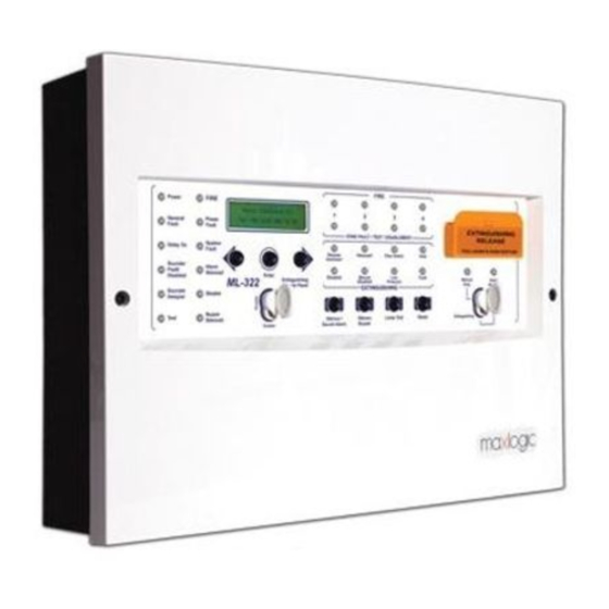
Figure 24-Panel’s front side 19.1 PANEL’S INDICATORS 19.1.1 General LED’s Power “Power” LED permanently illuminates when system energized. Fire “Fire” LED permanently illuminates when fire alarm condition continuous. KK-642.041 Rev No:1 01.08.12 ML-322 Maxlogic fire extinguishing panel operating manual Page 36/53... - Page 37 The operating types of the extinguishing LED’s have been shown at the table below. Detailed information about these listed extinguishing conditions has been described on “Extinguishing Conditions” section. KK-642.041 Rev No:1 01.08.12 ML-322 Maxlogic fire extinguishing panel operating manual Page 37/53...
- Page 38 When there is a fault of a device on any of the detection zone related fault led has been flashed. If any of the detection zone has been disabled or test operation is performing, fault LED illuminates permanently. KK-642.041 Rev No:1 01.08.12 ML-322 Maxlogic fire extinguishing panel operating manual Page 38/53...
- Page 39 Right Arrow Button If user does not enter any menu step, this button has been used to select event and countdown time. If user has been entered KK-642.041 Rev No:1 01.08.12 ML-322 Maxlogic fire extinguishing panel operating manual Page 39/53...
-
Page 40: Extinguishing Status Indicator Unit
The connection between ML-322 and extinguishing status indication unit should be controlled. Up to 8 pieces of extinguishing status indicator units have been connected to a single ML-322 fire extinguishing panel. An address value between 1 to 8 has been assigned to each extinguishing status indicator unit. -
Page 41: Figure 25-Connection Between Panel And Extinguishing Status Indicator Units
Extinguishing Figure 25-Connection between panel and extinguishing status indicator units This unit operates by 24V DC supplied voltage and communicates with fire extinguishing panel via network card. KK-642.041 Rev No:1 01.08.12 ML-322 Maxlogic fire extinguishing panel operating manual Page 41/53... -
Page 42: Operations On The Periodic Maintenance
Cleaning operation, connection controls and tests of the photo-electric smoke detectors whose planned maintenance control date have been reached should be done. Customer’s technical service personal have been trained for the unreachable ones. KK-642.041 Rev No:1 01.08.12 ML-322 Maxlogic fire extinguishing panel operating manual Page 42/53... - Page 43 5. During the whole periodic maintenance operations fire panel’s sounders have been tested. 6. During the whole periodic maintenance operations the functions (dampers, valves with motor, elevators etc.) which are commanded from panel have been controlled. KK-642.041 Rev No:1 01.08.12 ML-322 Maxlogic fire extinguishing panel operating manual Page 43/53...
-
Page 44: Annex - Ml-321 Series Panel Structure
KK-642.041 Rev No:1 01.08.12 ML-322 Maxlogic fire extinguishing panel operating manual Page 44/53... -
Page 45: Annex - Ml-322 Series Panel Structure
KK-642.041 Rev No:1 01.08.12 ML-322 Maxlogic fire extinguishing panel operating manual Page 45/53... -
Page 46: Annex - Lcd Messages
3 1 / 0 3 / 1 1 0 9 : 5 7 Year Hour Minute (*): Events are separated by 2 groups as fire events and other events. KK-642.041 Rev No:1 01.08.12 ML-322 Maxlogic fire extinguishing panel operating manual Page 46/53... -
Page 47: Annex - 2Nd Access Level Menu Structure
Enable / Disable Zone 3 Test Zone 4 Test Enable / Disable Low Pressure Input Enable / Disable Enable / Disable Manuel Extinguishing Enable / Disable Extinguishing System KK-642.041 Rev No:1 01.08.12 ML-322 Maxlogic fire extinguishing panel operating manual Page 47/53... -
Page 48: Annex - 3Rd Access Level Menu Structure
Enable / Disable Ground Fault Enable / Disable Unsuccesful Ext. Det. Delay Reset Enable / Disable Enable / Disable Man.Ext.Abort Cal Point Zone 1 Dly. Device Detector KK-642.041 Rev No:1 01.08.12 ML-322 Maxlogic fire extinguishing panel operating manual Page 48/53... - Page 49 Zone 3 Dly. Device Cal Point Detector No Delay Zone 4 Dly. Device Cal Point Detector No Delay Res.Eng.Time 0 - 30 min. Ext. Delay 0 - 10 min. KK-642.041 Rev No:1 01.08.12 ML-322 Maxlogic fire extinguishing panel operating manual Page 49/53...
- Page 50 Ext. Time 30 - 300 sec. / Permenant Date xx/xx/xx xx:xx Time Print Event Log Delete Event Log Abort Type Abort / Res.and Abort KK-642.041 Rev No:1 01.08.12 ML-322 Maxlogic fire extinguishing panel operating manual Page 50/53...
-
Page 51: Annex - De�Initions Of The Terms
Fault R Fault Relay Fire S Fire Signal Fault S Fault Signal Zone 1 Zone 2 Zone 3 Zone 4 Delay Reset Manuel Extinguishing Low Pressure Mode Selection KK-642.041 Rev No:1 01.08.12 ML-322 Maxlogic fire extinguishing panel operating manual Page 51/53... -
Page 52: Annex - Mechanical And Outer Environment Speci�Ications
21±1 Volt Battery power off voltage 19±1 Volt Full battery output current (Imaxb) Empty battery output current (Imaxa) 3,9 A Maximum battery internal resistance (Ri max) 0,55 Ω KK-642.041 Rev No:1 01.08.12 ML-322 Maxlogic fire extinguishing panel operating manual Page 52/53... -
Page 53: Annex - Input / Output Speci�Ications
Cable condition for reserved 24V output There is no any force, the capacity must be 250mA. The minimum voltage level must be higher than used device’s operating limit after connection. KK-642.041 Rev No:1 01.08.12 ML-322 Maxlogic fire extinguishing panel operating manual Page 53/53...
Need help?
Do you have a question about the ML-322 and is the answer not in the manual?
Questions and answers