
Related Manuals for Maxlogic ML-121X


Summary of Contents for Maxlogic ML-121X
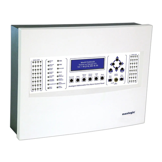
- Page 1 COMMISSIONING, OPERATING AND MAINTENANCE MANUAL ML-121X MODEL: MAXLOGIC SERIES SUB MODEL: INTELLIGENT ANALOGUE ADDRESSABLE FIRE ALARM CONTROL PANEL...
-
Page 2: Table Of Contents
ANNEX-A PANEL DIMENSIONS AND MOUNTING HOLES ................28 ANNEX-B CONNECTION SCHEME ......................29 ANNEX-C PANEL SPARE PARTS ........................ 30 ANNEX-D SERIAL COMMUNICATION CABLE ..................... 31 ANNEX-E SCHEME OF MENU FUNCTIONS ....................32 ANNEX-F NETWORK CONNECTION SCHEME .................... 36 KK-641.002 Rev.No:1 01.08.12 ML-121X User Manual Page | 2... -
Page 3: 1- Introduction
24V DC 500mA auxiliary power supply output. Furthermore, 4 remote control inputs (alarm, silence/sound alarm, reset and fault) exist in the panel. ML-121X series fire alarm control panels have the optional functions described in TS EN 54-2 standards;... -
Page 4: 2- Warnings
Screws or bolts of a minimum of 4mm diameter must be used to mount the cabinet in all four mounting positions. Drill and plug the wall then fix the cabinet using all fixing points. KK-641.002 Rev.No:1 01.08.12 ML-121X User Manual Page | 4... -
Page 5: 4- Panel Inputs
Annex-B, Figure-14. 4.3 Detection Devices Inputs (Loop Lines) ML-121X series panels are produced with 0, 1, 2 loop models. Panels with 0 loops (no-loop) are used as repeater panels. Each loop is capable of hosting up to 127 addressable devices. Connection of loop line to the control panel must be as like in Annex-B, Figure-7. -
Page 6: Panel Pc Connection
Otherwise, open circuit fault is monitored on the sounder line of panel. In case of any open circuit or short circuit faults occurred, it can be displayed on the screen of panel with the line number. KK-641.002 Rev.No:1 01.08.12 ML-121X User Manual Page | 6... -
Page 7: Auxiliary Power Supply Output (24 V Dc)
In case of high current driven applications, the relay outputs can get damage if there is no contactor. This situation is not subjected to the warranty condition. KK-641.002 Rev.No:1 01.08.12 ML-121X User Manual Page | 7... -
Page 8: 6- Panel Buttons And Indicators
Reset : Resets all existing fire and fault events in the system. Fire and Fault relays are brought to normal position (if fire and fault condition is not proceeding). KK-641.002 Rev.No:1 01.08.12 ML-121X User Manual Page | 8... - Page 9 Microprocessor Reset: Microprocessor can be reset by pressing the ‘Microprocessor Reset’ button. (ANNEX-B, Figure-13) LCD Lighting : Used to adjust the LCD display contrast with the aid of trimpot (ANNEX-B, Figure-10). KK-641.002 Rev.No:1 01.08.12 ML-121X User Manual Page | 9...
-
Page 10: Front Panel Indicators
Zone Disablement : It indicates that one or more zones are disabled from the panel menu. It illuminates as ‘Yellow’. More Events : If there is more than one event in the system this LED illuminates as ‘Yellow’. KK-641.002 Rev.No:1 01.08.12 ML-121X User Manual Page | 10... -
Page 11: Internal Indicators
3A self-resetting fuse becomes active upon short circuit in 28 V output of power supply. In this case, the outputs of power supply become de-energized. Note: the placement of the fuses is shown in Annex-B. KK-641.002 Rev.No:1 01.08.12 ML-121X User Manual Page | 11... -
Page 12: 8- Powering The Panel
Re-Initiate System (Automatic Learning) PC Program Use Valid Data (In case the panel is energized for the first time, panel memory is empty and this option cannot be selected at the first system boot.) KK-641.002 Rev.No:1 01.08.12 ML-121X User Manual Page | 12... - Page 13 8.1.4.2. PC Program A special software program called ‘Loop Manager’ is used for programming the panel. Creating zone location texts, creating cause-effect scenarios, device settings etc. are all done through ‘Loop Manager’ Software. KK-641.002 Rev.No:1 01.08.12 ML-121X User Manual Page | 13...
- Page 14 Data transfer can be initiated through the Loop Manager; there is no need to follow any procedure on the panel. It is sufficient to click on ‘Start Downloading’ Button. When data transfer completed, the following comment is displayed on the program; KK-641.002 Rev.No:1 01.08.12 ML-121X User Manual Page | 14...
- Page 15 8.1.5. Booting panel: At the end of automatic learning or computer/panel communication, system boots in normal operation mode. On the LCD screen of the panel following comment is seen; KK-641.002 Rev.No:1 01.08.12 ML-121X User Manual Page | 15...
-
Page 16: Booting Previously Configured Panel
8.2.2. Reconfiguring the panel: Reconfiguring of an already existing panel may be necessary for some reasons like adding new device(s), removing device(s), updating zone location text information and changing device settings etc. KK-641.002 Rev.No:1 01.08.12 ML-121X User Manual Page | 16... -
Page 17: 9- Fire Event Message Format On Panel Lcd Screen
4. In the 4 row; zone name of the device where fire alarm comes is displayed. KK-641.002 Rev.No:1 01.08.12 ML-121X User Manual Page | 17... -
Page 18: 10- Fault Event Message Format On Lcd Screen
ACCESS LEVEL 2 MENU INSTRUCTIONS +DEVICES: The following information for the devices connected to every single loop can be displayed: Address information, zone location texts, device models, analogue values, status of devices (Enabled/Disabled). KK-641.002 Rev.No:1 01.08.12 ML-121X User Manual Page | 18... - Page 19 The followings are available settings to be made. -Panel General Settings: -Supplier Name: The company name (and contact information) information which will be displayed on panel screen in normal operating mode can be KK-641.002 Rev.No:1 01.08.12 ML-121X User Manual Page | 19...
- Page 20 -Global Silence: When selected as active; all outputs can be silenced by pressing ‘Silence Alarm’ button. When selected as passive; only devices, which are marked as “Yes” for “Is silenceable Output?” parameter to be accessed through Loop KK-641.002 Rev.No:1 01.08.12 ML-121X User Manual Page | 20...
- Page 21 +View by Category: The event logs are displayed as being categorized depending on the event types. Fires: x Evacuates: x Faults: x Pre-Alarms: x -View by list: All events are sorted. KK-641.002 Rev.No:1 01.08.12 ML-121X User Manual Page | 21...
- Page 22 _ _ _ _ _ _ _ _ _ _ _ _ _ _ _ _ _ _ _ _ _ _ _ E x i L e f : B a KK-641.002 Rev.No:1 01.08.12 ML-121X User Manual Page | 22...
-
Page 23: 12- Networking Principles
Note: See, Annex-E Menu Functions Scheme for switch between menu functions. 12- NETWORKING PRINCIPLES So that Maxlogic series fire alarm control panels can operate in network, each panel must contain 1 unit of ML-1201 Network Module. Please, see Section “15- Panel Models” which includes ML-121X.N models having network module by default. - Page 24 Furthermore, one panel can control other panels (Reset, Silence Sounder etc.) All models of Maxlogic Series Fire Alarm Control Panels can operate in the same network. (ML-121X.N, ML-123X.N, ML-124X.N, ML-125X.N) ** GCU (Gateway Controller) allows the network to be monitored graphically and controlled remotely from a distant place.
- Page 25 Used for signal amplifying distance extender Mode modules 120R disabled End-of-Line Resistor Setting Used to activate 120R which is the end-of-line 120R enabled resistor. Always, it must be at this position KK-641.002 Rev.No:1 01.08.12 ML-121X User Manual Page | 25...
-
Page 26: 13- Technical Specifications
Finish : Surface or flush mount Mounting : Grey (RAL 7015), white panel front cover Standard color : 500 x 370 x 110 mm Dimensions : max. 7.650 kg Weight : KK-641.002 Rev.No:1 01.08.12 ML-121X User Manual Page | 26... -
Page 27: 14- Panel Models
Maxlogic intelligent analogue addressable fire alarm panel, 0 Loop, Network, 230V AC, 50 Hz, 83 Watt, IP30 ML-1211 Maxlogic intelligent analogue addressable fire alarm panel, 1 Loop, 127 Address, 230V AC, 50 Hz, 83 Watt, IP30 Maxlogic intelligent analogue addressable fire alarm panel, 1 Loop, 127 Address, Network, 230V AC, 50 Hz, ML-1211.N... -
Page 28: Annex-A Panel Dimensions And Mounting Holes
ANNEX-A PANEL DIMENSIONS AND MOUNTING HOLES Figure 1- Panel Dimensions Figure 2- Mounting Holes KK-641.002 Rev.No:1 01.08.12 ML-121X User Manual Page | 28... -
Page 29: Annex-B Connection Scheme
ANNEX-B CONNECTION SCHEME KK-641.002 Rev.No:1 01.08.12 ML-121X User Manual Page | 29... -
Page 30: Annex-C Panel Spare Parts
ANNEX-C PANEL SPARE PARTS KK-641.002 Rev.No:1 01.08.12 ML-121X User Manual Page | 30... -
Page 31: Annex-D Serial Communication Cable
ANNEX-D SERIAL COMMUNICATION CABLE KK-641.002 Rev.No:1 01.08.12 ML-121X User Manual Page | 31... -
Page 32: Annex-E Scheme Of Menu Functions
ANNEX-E SCHEME OF MENU FUNCTIONS KK-641.002 Rev.No:1 01.08.12 ML-121X User Manual Page | 32... - Page 33 KK-641.002 Rev.No:1 01.08.12 ML-121X User Manual Page | 33...
- Page 34 KK-641.002 Rev.No:1 01.08.12 ML-121X User Manual Page | 34...
- Page 35 KK-641.002 Rev.No:1 01.08.12 ML-121X User Manual Page | 35...
-
Page 36: Annex-F Network Connection Scheme
ANNEX-F NETWORK CONNECTION SCHEME KK-641.002 Rev.No:1 01.08.12 ML-121X User Manual Page | 36...
Need help?
Do you have a question about the ML-121X and is the answer not in the manual?
Questions and answers