Table of Contents
Advertisement
Quick Links
User Manual
3 Axis Ultrasonic Anemometers
1590-PK-020/W (WindMaster) with Firmware 2329-701 and higher
1561-PK-020/W (WindMaster Pro) with Firmware 2329-701 and higher
1590-PK-130/W (WindMaster RA) with Firmware 2329-701 and higher
Document Number: 1561-PS-0001 Issue 17
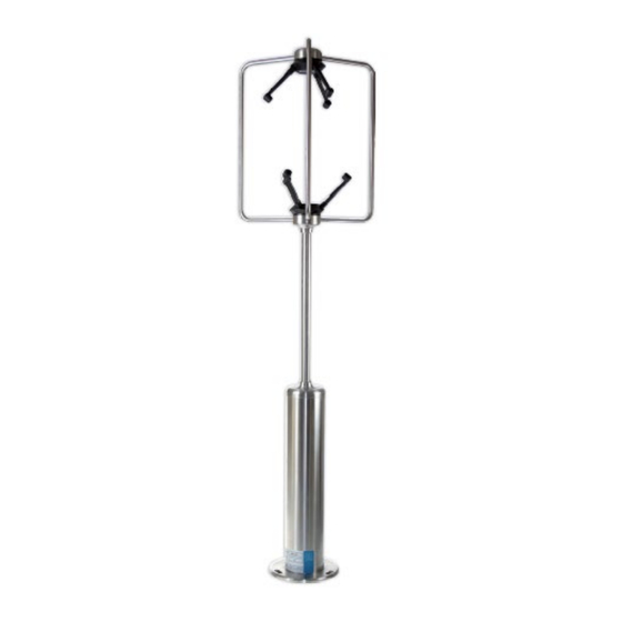
WindMaster
Email:
anem@gillinstruments.com
gillinstruments.com
1561-PS-0001 Issue 17
© 2022 Gill Instruments Limited
WindMaster RA
Gill Instruments Limited
Saltmarsh Park, 67 Gosport Street, Lymington,
Hampshire, SO41 9EG, UK
Tel: +44 1590 613500, Fax: +44 1590 613555
Website:
1
WindMaster Pro
www.gillinstruments.com
Advertisement
Table of Contents

Related Manuals for Gill Instruments WindMaster


Summary of Contents for Gill Instruments WindMaster
- Page 1 User Manual 3 Axis Ultrasonic Anemometers 1590-PK-020/W (WindMaster) with Firmware 2329-701 and higher 1561-PK-020/W (WindMaster Pro) with Firmware 2329-701 and higher 1590-PK-130/W (WindMaster RA) with Firmware 2329-701 and higher Document Number: 1561-PS-0001 Issue 17 WindMaster Pro WindMaster WindMaster RA Gill Instruments Limited...
-
Page 2: Table Of Contents
Cable Length ..........................15 4.5. Grounding (Earthing) ........................15 4.6. Connections ..........................15 4.6.2. Connection Details and WindMaster and WindMaster Pro Pipe Mount Box Connection Details (Spared Item 1590-PK-048)......................... 17 4.7. Connection to PC using RS232 ..................... 20 4.8. - Page 3 Appendix C - WindMaster Default Setup ..................54 Appendix D - Configuring ........................55 Appendix E - Viewing and logging WindMaster Data using Gill WindView Software ....70 Appendix F - Status (error) Codes ....................... 74 Appendix G - Maintenance & Fault-Finding ..................75 Appendix H - Tests ..........................
-
Page 4: Welcome To The Windmaster User Manual
This manual describes the operation of the WindMaster (1590-PK-020/W + options), WindMaster RA (1590-PK-130/W + options) and WindMaster Pro (1561-PK-020/W + options). The term 'WindMaster' is used in this manual as a general term for both the WindMaster and the WindMaster Pro; they are robust three axis anemometers, with no moving parts. -
Page 5: User Manual Revision History
General Notes Before WindMaster is used for the first time it is essential to read and understand this manual. Please keep the manual safe for future reference. Care should be taken with WindMaster at all times. The product should be transported to site in the box, and only removed when ready to install. -
Page 6: Principle Of Operation
2. Principle of Operation The WindMaster measures the times taken for an ultrasonic pulse of sound to travel from an upper transducer to the opposite lower transducer and compares it with the time for a pulse to travel from lower to upper transducer. - Page 7 +W is defined as vertically up the mounting shaft. Note, when the unit is configured for the X2 setting the UV definition rotates 30 degrees anti-clockwise such that U is now in line with transducer axis 1. gillinstruments.com 1561-PS-0001 Issue 17 © 2022 Gill Instruments Limited...
- Page 8 Figure 2 U, V and W Axis Definition X1 Setting UV Alignment X2 Setting U Alignment to Transducer 1 gillinstruments.com 1561-PS-0001 Issue 17 © 2022 Gill Instruments Limited...
- Page 9 The table shows the firing sequence of the transducers. Measurement Sequence The sample rate is automatically selected to either 20Hz or 32Hz, depending on the output rate configured See Appendix D (configuring WindMaster using a Terminal Program e.g. Tera Term). Measurement Period Max 50mS (at 20Hz) or 31.25mS (at 32Hz)
- Page 10 Signal processing Instantaneous Sampling The WindMaster can be configured to output the sampled data direct at the selected output rate without any averaging -"Instantaneous sampling". Alternatively, data can be sampled at 20Hz or 32Hz and averaged (see Appendix D, page 68: Fx y and Px).
-
Page 11: Pre-Installation
, and is strongly recommended as it provides an easy, user- friendly interface to configure the WindMaster range units. software available free at www.gillinstruments.com , and it provides an interface to view and log WindMaster INDVIEW Range data. 3.3. Ordering Options These options must be specified when ordering the WindMaster Range Units. -
Page 12: Accessories
3.5. Packing Whilst the WindMaster Range unit is being moved to its installation site, the unit should be kept in its packaging. All the packaging should be retained for use if the unit has to be returned at any time. -
Page 13: Installation
(See Sections 4 and 5). Connection The WindMaster/RA/Pro unit is fitted with a 31-way Clipper industrial plastic socket and supplied with a Gill modified 31-way mating plug (shell size 3). The cable should be securely fixed with cable clamps or equivalent, so that the cable is not under stress at the plug. -
Page 14: Bench System Test
4.2. Bench System Test Prior to physically mounting the WindMaster Range Unit in its final location, we strongly recommend that a bench system test be carried out to confirm the system is configured correctly, is fully functional and electrically compatible with the selected host system and cabling (preferably utilising the final cable length). -
Page 15: Cable Length
The integrity of the screen of each pair should be maintained throughout the cable run. Avoid long grounding loops. For maximum lightning protection it is essential that the unit be properly grounded via its mounting base. gillinstruments.com 1561-PS-0001 Issue 17 © 2022 Gill Instruments Limited... - Page 16 4.6.1. Base Connector WindMaster 1590-PK-020/W), WindMaster RA 1590-PK-130/W, WindMaster Pro 1561-PK- 020/W). 31- Way Base Connector Function Remarks 31-way Connector Pin No TXA (-) Anemometer Transmit - TXB (+) Anemometer Transmit + RXB (+) Anemometer Receive + RXA (-) Anemometer Receive -...
-
Page 17: Connection Details And Windmaster And Windmaster Pro Pipe Mount Box Connection Details (Spared Item 1590-Pk-048)
4.6.2. Connection Details and WindMaster and WindMaster Pro Pipe Mount Box Connection Details (Spared Item 1590-PK-048). See also the next page. Part Pipe Mount Adaptor 1590-PK-048 Spared Item Connector Terminal Connection Name PRT Excite + (wired connection) PRT Excite – (wired connection) PRT Sense + (wired connection) PRT Sense –... - Page 18 WindMaster 1590-PK-048 Pipe Mount Box Connection Schematic J4, Comms Link Positions. Solid line is default (COM to CM). Move to COM and V+ for RS232 only if not using an external wire link to set RS232 operation. Move to COM and 0V for RS422/RS485 only if not using an external wire link to set RS422/RS485 operation...
- Page 19 The M20 cable gland outlet on the Pipe Mount box is designed to accept cables with an outer diameter between 8mm to 13mm. 31 Way Connector to PCB Wiring Loom Details 31 Way Connector gillinstruments.com 1561-PS-0001 Issue 17 © 2022 Gill Instruments Limited...
-
Page 20: Connection To Pc Using Rs232
See 4.4 Using RS232, the cable length for reliable operation is limited to 6.5m (20ft) @ 9600 Baud. For longer cable runs, we recommend using the WindMaster configured with RS422 output, and a RS422/232 converter at the PC. See Appendix D Configuring. -
Page 21: Connection To A Pc Using Rs422
J4 link from COM/CM to between COM and 0v. 3. Configure WindMaster for RS 422 by linking Comms Mode line (Pin 4) to 0V (Pin 12). 4. On non-pipe mount box units if Pin 4 is left open circuit the unit will default to RS422 operation in Auto mode. -
Page 22: Connection To A Pc Using Rs485
4.9. Connection to a PC using RS485 These notes apply to using WindMasters and WindMaster Pro’s only on a 2 wire RS485 network. Set up the WindMaster operating configuration before wiring for RS485 mode. WindMasters must be configured for RS485 by linking Comms Mode line (Pin 4) to 0V (Pin 12). -
Page 23: Mechanical Installation
Select a position so that the unit is clear of any structure, which may obstruct the airflow or induce turbulence. Do NOT mount the WindMaster in close proximity of high-powered radar or radio transmitters. A site survey may be required if there is any doubt about the strength of external electrical noise. - Page 24 Figure 3 North Spar Alignment and Dimensions WindMaster Pro gillinstruments.com 1561-PS-0001 Issue 17 © 2022 Gill Instruments Limited...
- Page 25 North Spar, Marker Symbol and Notch gillinstruments.com 1561-PS-0001 Issue 17 © 2022 Gill Instruments Limited...
- Page 26 Grounding (Earthing) For protection against lightning the WindMaster MUST be earthed via its mountings. The unit MUST be connected to an appropriate grounding point with a minimum of 6mm² copper wire.
- Page 27 Gill Instruments Pipe mount adaptor (1561-PK-026). The pipe mount adaptor made of mild steel with a zinc passivate, enables the WindMaster to be fitted directly to a standard 1.5 inch BSP pipe (Pipe size OD 1.9" (48.3mm) , ID 1.5" (38.1mm) , wall thickness 0.2" (5.08mm). The pipe mount adaptor can be ordered from Gill.
- Page 28 3 holes tapped for M6 bolts, equi-spaced on a 85.0 PCD 2 holes tapped for M8 bolts Figure 5. Pipe Mount Adaptor (1561-PK-026) gillinstruments.com 1561-PS-0001 Issue 17 © 2022 Gill Instruments Limited...
- Page 29 Gill Pipe Mount Adaptor Part 1590-PK-048 can be used with WindMaster and WindMaster Pro units. A kit parts are supplied that can be assembled to the base of the WindMaster/Pro and to complete mounting the assembled unit to a pipe.
- Page 30 The unit MUST be connected to an appropriate grounding point with a minimum of 6mm² copper wire. An M6 ring terminal is fitted to the WindMaster as illustrated above to which the 6mm² copper wire can be crimped attached for connection to a ground point.
-
Page 31: Message Formats
5. Message Formats On applying power to the WindMaster, it will automatically operate in the Measurement Mode and provide wind measurements in one of the following formats: Mode 1 – ASCII, UVW, Continuous Mode 2 – ASCII, Polar, Continuous (default format) ... -
Page 32: Mode 1 - Ascii, Uvw Continuous
PRT temperature in degrees C, e.g. +23.13deg C output as +23.13C in the string. <ETX> End of string character (ASCII value 3) Checksum of all Characters between <STX> and <ETX> (HEX byte) <CR><LF> Carriage Return and Line Feed gillinstruments.com 1561-PS-0001 Issue 17 © 2022 Gill Instruments Limited... - Page 33 <STX> Start of string character (ASCII value 2). WindMaster Identification node address The default setting is ‘Q’. Horizontal wind speed . See Fig 2. Shows the wind speed in the U / V Plane Vertical wind speed . See Fig 2.
- Page 34 Output rate (not displayed) The WindMaster delivers wind information at rates from 1 (default setting) to 32 outputs / second. [The sample rate (20 or 32 Hz) is chosen automatically to be an appropriate multiple of the output rate.] Data can be instantaneous or averaged (see section Appendix D).
-
Page 35: Mode 2 - Ascii, Polar, Continuous (Default Output Parameters In Red)
Parameters are as described in Para 5.1 except that: - Horizontal wind direction Indicated in degrees, from 0 to 359°, with respect to the WindMaster North marker. In fixed field mode and when the wind speed is below 0.05 metres/sec, the direction will not be calculated, but the last calculated direction above 0.05 m/s will be output (the threshold of 0.05 m/s is the default setting;... -
Page 36: Mode 3 - Ascii, Uvw, Polled
PRT temperature in degrees C, e.g., +23.13deg C output as +23.13C in the string. <ETX> End of string character (ASCII value 3) Checksum of all Characters between <STX> and <ETX> (HEX byte) <CR><LF> Carriage Return and Line Feed gillinstruments.com 1561-PS-0001 Issue 17 © 2022 Gill Instruments Limited... -
Page 37: Polled Mode Notes General
WindMaster Unit Identifier – that is, the relevant letter A – Z. The default setting is ‘Q’. It is recommended that letters A to F, K, M, N, and P are not used since they can appear in a WindMaster data string and might result in erroneous poll responses. - Page 38 Receipt of poll command will trigger a single 50mS or 31.25mS ultrasonic measurement and at the same time will trigger a Wind measurement output resultant from the previous polled measurement. The minimum Poll command rate is 20Hz. Analogue inputs are not supported in Syncpoll 1 mode. gillinstruments.com 1561-PS-0001 Issue 17 © 2022 Gill Instruments Limited...
-
Page 39: Mode 4 - Ascii, Polar, Polled
Data is 2 byte signed two’s complement (except unsigned for SOS; 1 byte for checksum). Velocities are normal resolution (0.01m/s). Outputs that are disabled are padded with zero to give fixed size records. A Gill Binary to ASCII Converter is available to download from http://gillinstruments.com/main/software.html gillinstruments.com 1561-PS-0001 Issue 17 © 2022 Gill Instruments Limited... -
Page 40: Mode 8 - Binary, Uvw, Short
Status data (Codes 00 to 0B) Wind Direction Wind Speed W axis velocity Speed of Sound in 0.01ms -1 Analogue input 1 Analogue input 2 Analogue input 3 Analogue input 4 Platinum Resistance Thermometer input CHECKSUM gillinstruments.com 1561-PS-0001 Issue 17 © 2022 Gill Instruments Limited... -
Page 41: Mode 10 - Binary, Uvw, Long
SoS is always reported as Speed of Sound independent of A command setting. TPrt is always reported independent from the V command setting. A1 to A4 are always reported independent from the I command setting. gillinstruments.com 1561-PS-0001 Issue 17 © 2022 Gill Instruments Limited... -
Page 42: Analogue Inputs
For pin connections The WindMaster can be configured for 4 single analogue inputs (31-way connector Pins 27, 28, 29 and 24 or on Pipe mount box A IN 1, A IN 2, A IN 3, and A IN 4) or 2 differential analogue inputs. 31-way connector Input 1 (Pins 27 and 28) and Input 2 (Pins 29 and 24) or Pipe Mount box Input 1 (A IN 1 and A IN 2) and Input 2 (A IN 3 and A IN 4). -
Page 43: Input Rates
0 - 20mA. 7.3. Voltage Outputs The output impedance is less than 1 ohm. To prevent inaccuracies, the outputs should be connected to an input with an impedance greater than 10KΩ. gillinstruments.com 1561-PS-0001 Issue 17 © 2022 Gill Instruments Limited... -
Page 44: Current Outputs
+2.50 +5.0 20.00 20.00 359.9° 540° wraparound 0.00 -2.50 -5.0 4.00 0.00 0° 1.67 -0.83 -1.66 9.33 6.67 180° 3.33 +0.83 +1.66 14.67 13.33 360° 5.00 +2.50 +5.0 20.00 20.00 539.9° gillinstruments.com 1561-PS-0001 Issue 17 © 2022 Gill Instruments Limited... - Page 45 If a unit has analogue outputs, then the factory settings are: - Channel 1 0-5v, Polar Wind Angle, 0-360 degrees. Channel 2 0-5v, Polar Wind Speed, 0-5m/s. Channel 3 0-5v, W Wind Speed, 0-5m/s. Channel 4 0-5v, Status. gillinstruments.com 1561-PS-0001 Issue 17 © 2022 Gill Instruments Limited...
-
Page 46: Appendix A - Technical Specification
Appendix A - Technical Specification WindMaster/WindMaster Pro Accuracy specification applies for wind speed up to range maximum, and for wind incidence up to ± 30 ° from the horizontal on units with firmware 2329-700 and higher. Custom calibration (to be specified when ordering, or unit can be returned for calibration) - Page 47 PRT (Optional) WindMaster/WindMaster RA WindMaster Pro Resolution Not Applicable 0.1°C Measurement Accuracy Not Applicable <±0.1°C (-40 to +50°C) <±0.15°C (+50 to +70°C) Software Wind Configuring & monitoring WindView Monitoring & logging gillinstruments.com 1561-PS-0001 Issue 17 © 2022 Gill Instruments Limited...
- Page 48 Emissions BS EN 61000 - 6 - 3 Immunity BS EN 61000 - 6 - 2 Precipitation Operation up to 300 mm / hour Humidity < 5 % to 100 % Protection Class IP65 gillinstruments.com 1561-PS-0001 Issue 17 © 2022 Gill Instruments Limited...
-
Page 49: Appendix B - Cable Assembly
Appendix B - Cable Assembly Preparation Open the pack of connector parts (1561-PK-050) provided with the WindMaster range unit. Note that the connector supplies the correct strain relief for cables with an outside diameter of 6-12mm. Trim back the screened cable outer and screen sleeves 50mm. - Page 50 Put the parts on the cable in the order as shown below. Put the parts on the cable in the order as shown below. Whilst squeezing the red retainers in the direction of ARROW A, pull in the direction of ARROW B. gillinstruments.com 1561-PS-0001 Issue 17 © 2022 Gill Instruments Limited...
- Page 51 Please note there will be some resistance. Continue to insert all the contacts you require in accordance with the diagram below. Connector Pin & Conductor positions. Supplied WindMaster Connector WindMaster Base socket gillinstruments.com 1561-PS-0001 Issue 17 © 2022 Gill Instruments Limited...
- Page 52 The retainer can only be pushed back into place if the contacts are fully engaged. Fit the connector to the WindMaster base so that you can now finish assembling the connector. Screw the back-shell onto the connector until it is fully in place. Please note that the final rotations can be slightly stiff.
- Page 53 Now screw the cable-clamping nut into place The connector can now be removed from the WindMaster. gillinstruments.com 1561-PS-0001 Issue 17 © 2022 Gill Instruments Limited...
-
Page 54: Appendix C - Windmaster Default Setup
Appendix C - WindMaster Default Setup Mode 2 – ASCII, Polar, Continuous ASCII, Polar+W, Continuous, <STX>Q,333,001.09,-001.70,M,00,<ETX>64 Node Direction Wind W axis Units Status Check address Magnitude velocity Degrees polarity Format for software configuring is:- <STX><ID>,DDD,MMM.MM,±WWW.WW,U,SS,<ETX>CC<CR><LF> Where: <STX> Start of string character (ASCII value 2) <ID>... -
Page 55: Appendix D - Configuring
Download the WIND software from the Gill website www.gillinstruments.com. With the WindMaster connected to the PC using one of the methods detailed in section 4, the opening menu will show the WindMaster in Measurement mode. A short Start message will be displayed, followed by continuous wind information displayed - the default setting being Polar, with the unit of measure Metres per second (m/s). - Page 56 If after Synch Comms there is still a problem with start-up, switch power to anemometer off and then on again and repeat procedure. The WindMaster is set to factory default 1 Hz output and in Polar mode. A typical message format after Synchronising Comms is shown below: gillinstruments.com...
- Page 57 When selected a similar message to that below will be displayed. To change the WindMaster configuration click Tools and Wizard in the tool bar Typical screens are shown below. It is possible to adjust all the settings as required taking into account the options selected at time of order (e.g., Analogue inputs and PRT).
- Page 58 1561-PS-0001 Issue 17 © 2022 Gill Instruments Limited...
- Page 59 When the changes are complete the Wizard will display a confirmation of the changes with all changes shown in red, this can be saved for future reference if required. Click next and the WindMaster will be re-configured and will return to measurement mode.
- Page 60 Stop bits 1 Flow Control (Handshaking) None Assuming the WindMaster has been correctly connected to the PC and a Power Supply, the opening menu will show the WindMaster in Measurement mode and scroll continuous wind information data. Entering Configuration mode...
- Page 61 ENTER . If successful, the new setting will be sent back as a message by the WindMaster. For example, to change the message format to UVW, Continuous, enter M 1 ENTER The WindMaster will reply M1. When the unit is returned to the Measurement mode, it will be in UVW, Continuous format.
- Page 62 E.g. If set to B3 (9600 baud), to change to B5 (38400 baud), enter B 5 ENTER , change host terminal to 38400 baud, and confirm by entering B ENTER. A random echo may be generated after the B confirmation request is sent by the WindMaster. Certain combinations of output rate, baud rate and message type may be unsupported.
- Page 63 Cx – Analogue output polar direction wrapping 540-degree wraparound on analogue output 360-degree wraparound on analogue output Dx – Diagnostic and configuration information Request serial number Request SW version Request current configuration Report DAC channel configuration gillinstruments.com 1561-PS-0001 Issue 17 © 2022 Gill Instruments Limited...
- Page 64 Configuration codes for Modes 02, 03, 04, and 09 equate to scale setting: - Config 01 = 5m/s Config 08 = 120m/s and Configuration code for Mode 5 equates to angle wrapping where: - Config 01 = 540° wraparound. Config 02 = 360° wraparound. gillinstruments.com 1561-PS-0001 Issue 17 © 2022 Gill Instruments Limited...
- Page 65 Calibration Off Calibration On Retries Enabled. WindMaster Default setting is ON. Enabled – If this mode is selected, if a problem sample is detected, the unit will attempt another ultrasonic firing within the set time parameters. Disabled – The unit will not attempt to re-check problem samples.
- Page 66 Default is OFF. Enabled – The WindMaster can be configured to output the sampled data direct at the selected output rate without any averaging -"Instantaneous Sampling". If for example the sensor is set for 1Hz output rate, then the unit will undertake one set of transducer firings and output the result after the 1 second period.
- Page 67 10 Binary, UVW, Long Nx – Set unit ID Sets the unit ID displayed at the start of all GILL communications strings Set Q (default), …from A to Z Command N<Q> gillinstruments.com 1561-PS-0001 Issue 17 © 2022 Gill Instruments Limited...
- Page 68 Q,251.7,000.860,-000.401,M,+346.43,+024.80,00,+2.4181,+2.4187,+2.4169,+2.4175,-50.00C,7F Q,999.9,999.999,+999.999,M,+999.99,+999.99,07,+2.4181,+2.4187,+2.4169,+2.4181,-50.00C,77 Px – Set output rate The P9 setting is an option on the WindMaster unit, which must be specified at the time of ordering. 18 Rate is 1 Hz (20Hz Sampling) 19 Rate is 2 Hz (20Hz Sampling)
- Page 69 Ux – Set units Knots Vx – Enable/Disable PRT PRT not available as an option for the WindMaster. Xx – Axis Alignment Align U Axis to unit North Spar (See Fig 2). Align U to the top axis transducer 1...
-
Page 70: Appendix E - Viewing And Logging Windmaster Data Using Gill Windview Software
Appendix E - Viewing and logging WindMaster Data using Gill WindView Software WindView can be downloaded from:- http://gillinstruments.com/main/software.html Open WindView and Select File/Connect. gillinstruments.com 1561-PS-0001 Issue 17 © 2022 Gill Instruments Limited... - Page 71 Select appropriate connection COM Port number and instrument Baud rate. Select output format UV or Polar to match the WindMaster setting. WindMaster 3 axis data will scroll on screen at the instruments output rate (2Hz shown). gillinstruments.com 1561-PS-0001 Issue 17...
- Page 72 Click on the WindSock tab to see a graphical display of wind. To Start Logging Data Note: If logging fast data of 20Hz or more ensure that the WindMaster is set for at least 38400 Baud. From the top menu click on Settings/Logging.
- Page 73 To Stop Logging Data When logging is required to stop go to the Top menu, Select File/Log/Stop. A typical logged Notepad file is as follows (WindMaster set for 2Hz output rate):- gillinstruments.com 1561-PS-0001 Issue 17 © 2022 Gill Instruments Limited...
-
Page 74: Appendix F - Status (Error) Codes
Insufficient samples in average period from all transducer pairs NVM Error NVM Checksum failed ROM Error ROM checksum failed System gain at Maximum Results OK, but marginal operation Retries Retries used gillinstruments.com 1561-PS-0001 Issue 17 © 2022 Gill Instruments Limited... -
Page 75: Appendix G - Maintenance & Fault-Finding
Corrupted output Try a slower baud rate. Check cable lengths and type of cable. Check WindMaster and host system are both set to the same protocol RS232, RS422, or RS485. One way communication Check wiring is in accordance with the manual. -
Page 76: Appendix H - Tests
Appendix H – Tests Bench Test • Couple the WindMaster to the host system and power supply, using a known working test cable. • Check that the unit is correctly configured Appendix D • Check for normal output data, and that the Status Code is OK – 00. - Page 77 Tera Term Setting up a WindMaster with or equivalent Terminal Program. Connect WindMaster (set/wired for RS232 or RS422/232/USB convertor in line) to the PC. Then open Tera Term as follows: - Select Serial and required port number. Click on OK.
- Page 78 Left click SETUP and use the drop-down menu to select ‘SERIAL PORT’. On the following screen. Set Bits per second drop down menu to the appropriate WindMaster baud rate setting e.g. 19200 bauds is the default WindMaster setting. Set Data Bits to 8.
- Page 79 The WindMaster should be outputting data as per the following screen. If strange characters or garbled data is observed in the data string, try opening Tera Term and selecting a different Baud rate (or connect the WindMaster in Wind to determine the Baud rate). To Communicate with the WindMaster: Type * (or hold down asterisk).
- Page 80 Certified Calibration The unit can be Wind tunnel calibrated in accordance with ISO 16622 with traceability to national standards. This should be specified when ordering, or the unit can be returned to Gill Instruments for retrospective calibration. Accuracy at 12 m/s Wind speed 1% RMS Direction 0.5...
-
Page 81: Appendix I - Guarantee
Appendix I - Guarantee For terms of guarantee contact your supplier or refer to the Gill Instruments Terms & Conditions here: https://gill.group/wp-content/uploads/Gill-Group-Company-Terms-Conditions-of-Sale-9170-0003-Issue-02-March- 20.._.pdf Warranty is void if the green security seal covering base nuts is damaged or broken, or the transducer caps have been damaged.
Need help?
Do you have a question about the WindMaster and is the answer not in the manual?
Questions and answers