Table of Contents
Advertisement
Quick Links
and
User Manual
3 Axis Ultrasonic Anemometers
1590-PK-020/W (WindMaster) with Firmware 2329-701 and higher
1561-PK-020/W (WindMaster Pro) with Firmware 2329-701 and higher
1590-PK-130/W (WindMaster RA) with Firmware 2329-701 and higher
1590-PK-050 (WindMaster Pipe Mount) with Firmware 2329-701 and higher
Document Number: 1561-PS-0001 Issue 11
WindMaster
Email:
anem@gillinstruments.com
WindMaster Pipe Mount
Gill Instruments Limited
Saltmarsh Park, 67 Gosport Street, Lymington,
Hampshire, SO41 9EG, UK
Tel: +44 1590 613500, Fax: +44 1590 613555
Website:
WindMaster RA
www.gillinstruments.com
Tel.: +11 3976-4003 • 3999-7737
vendas@romiotto.com.br
www.romiotto.com.br
WindMaster Pro
Advertisement
Table of Contents

Related Manuals for Gill Instruments 1561-PK-020


Summary of Contents for Gill Instruments 1561-PK-020
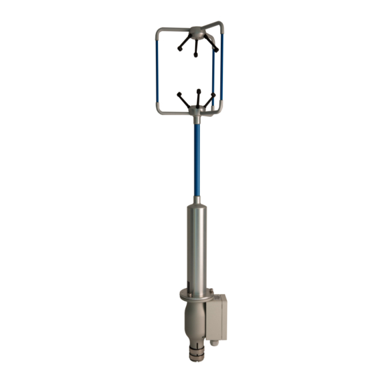
- Page 1 3 Axis Ultrasonic Anemometers www.romiotto.com.br 1590-PK-020/W (WindMaster) with Firmware 2329-701 and higher 1561-PK-020/W (WindMaster Pro) with Firmware 2329-701 and higher 1590-PK-130/W (WindMaster RA) with Firmware 2329-701 and higher 1590-PK-050 (WindMaster Pipe Mount) with Firmware 2329-701 and higher Document Number: 1561-PS-0001 Issue 11...
-
Page 2: Table Of Contents
6.10. Using RS485, 2 Wire, WindMaster/WindMaster Pro Networking 6.11. Mechanical installation Location Orientation Alignment and Dimensions Part 1590-PK-130 North Marker and WindMaster RA Dimensions Part 1590-PK-050 WindMaster Pipe Mount Dimensions Corrosion Grounding (Earthing) Mounting WindMaster (1590-PK-020/W +options and WindMaster Pro (1561-PK-020/W + options). 30 Cable strain relief... - Page 3 WindMaster and WindMaster Pro 1561-PS-0001. Issue 11 February 2017 ________________________________________________________________________________________________________________________ Flange mounting Gill Instruments Pipe mount adaptor (1561-PK-026). Gill Instruments WindMaster 1590-PK-050 Pipe Mount Adaptor. Gill Instrument Pipe Mount Adaptor 1590-PK-048. Grounding (Earthing) MESSAGE FORMATS 7.1. Mode 1– ASCII, UVW, Continuous...
- Page 4 WindMaster and WindMaster Pro 1561-PS-0001. Issue 11 February 2017 ________________________________________________________________________________________________________________________ 12.1 Bench test 12.2 Head Alignment Test 12.3 Calibration Standard calibration Certified calibration APPENDICES 13.1 Guarantee 13.2 Improvement Key Notes 13.3 Nakai 2012 Correction Information 13.4 Electrical Conformity Tel.: +11 3976-4003 • 3999-7737 vendas@romiotto.com.br www.romiotto.com.br...
-
Page 5: Foreword
________________________________________________________________________________________________________________________ 1. FOREWORD Thank you for purchasing a WindMaster or WindMaster Pro manufactured by Gill Instruments Ltd. The units have no customer serviceable parts and require no calibration or maintenance. To achieve optimum performance we recommend that you read the whole of this manual before proceeding with use. -
Page 6: Principle Of Operation
WindMaster and WindMaster Pro 1561-PS-0001. Issue 11 February 2017 ________________________________________________________________________________________________________________________ 3. PRINCIPLE OF OPERATION Figure 1 Time of Flight details The WindMaster measures the times taken for an ultrasonic pulse of sound to travel from an upper transducer to the opposite lower transducer, and compares it with the time for a pulse to travel from lower to upper transducer. -
Page 7: Polar Definition
WindMaster and WindMaster Pro 1561-PS-0001. Issue 11 February 2017 ________________________________________________________________________________________________________________________ Figure 2 shows the direction and polarity of the U, V and W axes. Polar definition The wind speed in the UV plane, with direction in degrees from 0 to 359 , with respect to the Reference spar (which is normally aligned to North). -
Page 8: Effects Of Temperature, Barometric Pressure, Rainfall And Humidity
WindMaster and WindMaster Pro 1561-PS-0001. Issue 11 February 2017 ________________________________________________________________________________________________________________________ Effects of temperature, barometric pressure, rainfall and humidity The calculated u, v and w components are independent of temperature, pressure, rainfall & humidity within the operating parameters of the WindMaster. The calculated sonic temperature/speed of sound should be corrected by the user for humidity to provide an indication of ambient temperature. -
Page 9: Specification
WindMaster and WindMaster Pro 1561-PS-0001. Issue 11 February 2017 ________________________________________________________________________________________________________________________ 4. SPECIFICATION Parameter WindMaster/WindMaster RA WindMaster Pro Outputs Output rate 0.25, 0.5,1, 2, 4, 8, 10, 16, 20, (32 0.25,0.5.1, 2, 4, 8, 10, 16, 20, 32 Hz option) Hz Sample rate (automatically selected) 20 or 32 Hz 20 or 32 Hz... - Page 10 General Weight 1.0kg (1590-PK-020 /W 1.7kg (1561-PK-020 /W) and 1590-PK-130/W). 2.12kg (1590-PK-050) Size 750mm x 240mm (1590-PK-020/W) 750mm x 240mm (1561-PK-020/W) 580mm x 323mm (1590-PK-130/W) 952mm x 240mm (1590-PK-050) Environmental IP65 IP65 Operating temperature -40 C to +70 C -40 C to +70 C Humidity <...
-
Page 11: Pre-Installation
(See Note 1) (See Note 1) standards (See Note 1) Note 1, Units may be returned to Gill Instruments for Wind tunnel calibration. Note 2, Implemented options are identified on the unit label with a against the option description. -
Page 12: Accessories
WindMaster and WindMaster Pro 1561-PS-0001. Issue 11 February 2017 ________________________________________________________________________________________________________________________ 5.4. Accessories Item Part No Travelling case - Portable protective case (WindMaster not for part 1590-PK- 1210 – 30 - 074 050) Travelling case - Portable protective case (WindMaster Pro) 1561 - 00 - 028 31 way Clipper connector 1561 - PK - 050... -
Page 13: Installation
WindMaster and WindMaster Pro 1561-PS-0001. Issue 11 February 2017 ________________________________________________________________________________________________________________________ 6. INSTALLATION 6.1. Installation Guidelines As with any sophisticated electronics, good engineering practice should be followed to ensure correct operation. Always check the installation to ensure the WindMaster is not affected by other equipment operating locally, which may not conform to current standards, e.g. -
Page 14: Cable Length
WindMaster and WindMaster Pro 1561-PS-0001. Issue 11 February 2017 ________________________________________________________________________________________________________________________ The table shows some suitable manufacturers’ references; other manufacturers’ equivalents can be used. No. of pairs Gill ref. Belden ref. Batt electronics ref. 026 - 02663 8774 91009 The cable allows for the connection of all: - Power inputs. -
Page 15: Connections
WindMaster and WindMaster Pro 1561-PS-0001. Issue 11 February 2017 ________________________________________________________________________________________________________________________ 6.6. Connections Important Do NOT join any of the cores of the cable together. Any cores not used should be isolated. Do NOT connect the unit’s analogue output 0V or power 0V to the screen or ground / earth. ... -
Page 16: Way Connector Cable Assembly
WindMaster and WindMaster Pro 1561-PS-0001. Issue 11 February 2017 ________________________________________________________________________________________________________________________ 31 Way Connector Cable Assembly. Open the pack of parts (1561-PK-050) provided with the WindMaster (not Pipe Mount units). Strip the cable and solder the contact pins to the cores (please note that the connector supplies the correct strain relief for cables with an outside diameter of 6-12mm). -
Page 17: Connector Pin & Conductor Positions
WindMaster and WindMaster Pro 1561-PS-0001. Issue 11 February 2017 ________________________________________________________________________________________________________________________ Insert each contact pin until you feel a slight click. If you have inserted the contact into the incorrect hole it can be removed at this point by simply pulling it out. Please note there will be some resistance. Continue to insert all of the contacts you require in accordance with the diagram below. - Page 18 WindMaster and WindMaster Pro 1561-PS-0001. Issue 11 February 2017 ________________________________________________________________________________________________________________________ Once all of the contacts are inserted push the red retainer into place. NB. The retainer can only be pushed back into place if the contacts are fully engaged. Fit the connector to the WindMaster so that you can now finish assembling the connector. Screw the back-shell onto the connector until it is fully in place.
-
Page 19: Windmaster 1590-Pk-050 Pipe Mount Box Connection Details And Windmaster And Windmaster Pro Pipe Mount Box Connection Details (Spared Item 1590-Pk-048)
WindMaster and WindMaster Pro 1561-PS-0001. Issue 11 February 2017 ________________________________________________________________________________________________________________________ 6.6.2 WindMaster 1590-PK-050 Pipe Mount Box Connection Details and WindMaster and WindMaster Pro Pipe Mount Box Connection Details (Spared Item 1590-PK-048). See also the next page. Part WindMaster 1590-PK-050 Pipe Mount Adaptor 1590-PK-048 Pipe Mount Integral Part Spared Item Connector... - Page 20 WindMaster and WindMaster Pro 1561-PS-0001. Issue 11 February 2017 ________________________________________________________________________________________________________________________ WindMaster 1590-PK-050 Pipe Mount Box Connection Schematic J4, Comms Link Positions. Solid line is default (COM to CM). Move to COM and V+ for RS232 only if not using an external wire link to set RS232 operation. Move to COM and 0V for RS422/RS485 only if not using an external wire link to set RS422/RS485 operation.
- Page 21 WindMaster and WindMaster Pro 1561-PS-0001. Issue 11 February 2017 ________________________________________________________________________________________________________________________ 31 Way Connector to PCB Wiring Loom Details Note:- WindMaster Part 1590-PK-050, the WindMaster 31 way connector wires 8, 9, 14, 14, 19, 20, 25 and 26 are not fitted. 31 Way Connector...
-
Page 22: Connection To A Pc Using Rs 232
WindMaster and WindMaster Pro 1561-PS-0001. Issue 11 February 2017 ________________________________________________________________________________________________________________________ 6.7. Connection to a PC using RS 232 Notes:- 1. Using RS232, the cable length for reliable operation is limited to 6.5m (20ft) @ 9600 Baud. See 6.4 2. For longer cable runs, we recommend using the WindMaster configured with RS422 output, and a RS422/232 converter at the PC. -
Page 23: Connection To A Pc Via A Power And Communications Interface Windmaster (1590-Pk-020/W +Options, Windmaster Ra 1390-Pk-130+Options And Windmaster Pro (1561-Pk-020/W + Options)
6.9. Connection to a PC via a Power and Communications Interface WindMaster (1590-PK-020/W +options, WindMaster RA (1590-PK-130/W) +options and WindMaster Pro (1561-PK-020/W + options). Dependent upon system requirements the WindMaster unit can be operated with the Power and Communications and Interface unit (PCI), which can be ordered as an optional extra. -
Page 24: Connector Pin And Cable Assignments For Pci/A
WindMaster and WindMaster Pro 1561-PS-0001. Issue 11 February 2017 ________________________________________________________________________________________________________________________ Connector Pin and Cable Assignments for PCI/A Anemometer Connector 15 - Way RS232 Output - 9 way Designation Designation Screen RS422_RXB (+) TX data RS422_TXB (+) RX data Digital 0V, Signal ground Supply V+ Signal Ground Analogue output V1... - Page 25 WindMaster and WindMaster Pro 1561-PS-0001. Issue 11 February 2017 ________________________________________________________________________________________________________________________...
-
Page 26: Using Rs485, 2 Wire, Windmaster/Windmaster Pro Networking
WindMaster and WindMaster Pro 1561-PS-0001. Issue 11 February 2017 ________________________________________________________________________________________________________________________ 6.10. Using RS485, 2 Wire, WindMaster/WindMaster Pro Networking Notes:- 1. These notes apply to using WindMasters and WindMaster Pro’s only on a 2 wire RS485 network. 2. Set up the WindMaster operating configuration before wiring for RS485 mode. 3. -
Page 27: Mechanical Installation
WindMaster and WindMaster Pro 1561-PS-0001. Issue 11 February 2017 ________________________________________________________________________________________________________________________ 6.11. Mechanical installation Before installing, it is strongly recommended that a bench test is carried out. Location Select a position so that the unit is clear of any structure, which may obstruct the airflow or induce turbulence. Do NOT mount the WindMaster in close proximity of high-powered radar or radio transmitters. -
Page 28: Part 1590-Pk-130 North Marker And Windmaster Ra Dimensions
WindMaster and WindMaster Pro 1561-PS-0001. Issue 11 February 2017 ________________________________________________________________________________________________________________________ Part 1590-PK-130/W North Marker and WindMaster RA Dimensions North Spar, Marker Symbol and Notch... -
Page 29: Part 1590-Pk-050 Windmaster Pipe Mount Dimensions
WindMaster and WindMaster Pro 1561-PS-0001. Issue 11 February 2017 ________________________________________________________________________________________________________________________ Part 1590-PK-050 WindMaster Pipe Mount Dimensions The North Spar and Alignment marking is illustrated in Figure 3 on the previous page. Corrosion Careful note should be taken of the possibility of galvanic corrosion by incorrect mounting. It is vital that only stainless steel fixings are used and that the instrument is insulated from the mounting surface with the rubber gasket. -
Page 30: Grounding (Earthing)
For protection against lightning the WindMaster MUST be earthed via its mountings. The unit MUST be connected to an appropriate grounding point with a minimum of 6mm² copper wire. Mounting WindMaster (1590-PK-020/W +options and WindMaster Pro (1561-PK-020/W + options). Connect Earth Lead to... -
Page 31: Gill Instruments Pipe Mount Adaptor (1561-Pk-026)
Issue 11 February 2017 ________________________________________________________________________________________________________________________ Gill Instruments Pipe mount adaptor (1561-PK-026). The pipe mount adaptor enables the WindMaster to be fitted directly to a standard 1.5 inch BSP pipe (Pipe size OD 1.9" (48.3mm) , ID 1.5" (38.1mm) , wall thickness 0.2" (5.08mm). The pipe mount adaptor can be ordered from Gill. -
Page 32: Gill Instruments Windmaster 1590-Pk-050 Pipe Mount Adaptor
Issue 11 February 2017 ________________________________________________________________________________________________________________________ Gill Instruments WindMaster 1590-PK-050 Pipe Mount Adaptor. WindMaster Part 1590-PK-050 is supplied with a Pipe Mount pre-assembled to the base of the WindMaster and with an installation kit box (part 1590-PK-045) to complete mounting the assembled unit to a pipe. -
Page 33: Gill Instrument Pipe Mount Adaptor 1590-Pk-048
WindMaster and WindMaster Pro 1561-PS-0001. Issue 11 February 2017 ________________________________________________________________________________________________________________________ Gill Instrument Pipe Mount Adaptor 1590-PK-048. Gill Pipe Mount Adaptor Part 1590-PK-048 can be used with WindMaster and WindMaster Pro units. A kit parts are supplied that can be assembled to the base of the WindMaster/Pro and to complete mounting the assembled unit to a pipe. -
Page 34: Grounding (Earthing)
WindMaster and WindMaster Pro 1561-PS-0001. Issue 11 February 2017 ________________________________________________________________________________________________________________________ Notes: The M20 Cable gland from the connection box is designed to accept cables with an outer diameter between 8mm to 13mm. Connect the external cable screen/s to the pillar inside the box using the supplied M4 parts illustrated above. Appropriate strain relief MUST be fitted to the cable connected through the M20 cable gland - this is particularly important with pipe mounting. -
Page 35: Message Formats
WindMaster and WindMaster Pro 1561-PS-0001. Issue 11 February 2017 ________________________________________________________________________________________________________________________ 7. MESSAGE FORMATS On applying power to the WindMaster, it will automatically operate in the Measurement Mode and provide wind measurements in one of the following formats: Mode 1 – ASCII, UVW, Continuous ... -
Page 36: Windmaster Identification Node Address
WindMaster and WindMaster Pro 1561-PS-0001. Issue 11 February 2017 ________________________________________________________________________________________________________________________ <STX> Start of string character (ASCII value 2). WindMaster Identification node address The default setting is ‘Q’. Horizontal wind speed Shows the wind speed in the U / V Plane. See Fig 2. Vertical wind speed Shows the magnitude of wind speed in the W axis. -
Page 37: Mode 2 - Ascii, Polar, Continuous (Default Output Parameters In Red)
WindMaster and WindMaster Pro 1561-PS-0001. Issue 11 February 2017 ________________________________________________________________________________________________________________________ (b) Mode 1 (High Resolution (J2)) ASCII, UVW, Continuous, Speed of Sound On, Sonic Temp On, [Analogue inputs On], PRT On <STX><ID>,±UUU.UUU,±VVV.VVV,±WWW.WWW,U,±CCC.CC,±TTT.TT, SS,[±1.1111,±2.2222,±3.3333,±4.4444],±PP.PPC,<ETX>CC<CR><LF> Where: <STX> Start of string character (ASCII value 2) <ID>... -
Page 38: Horizontal Wind Direction
WindMaster and WindMaster Pro 1561-PS-0001. Issue 11 February 2017 ________________________________________________________________________________________________________________________ Horizontal wind direction Indicated in degrees, from 0 to 359, with respect to the WindMaster North marker. In fixed field mode and when the wind speed is below 0.05 metres/sec, the direction will not be calculated, but the last calculated direction above 0.05 m/s will be output (the threshold of 0.05 m/s is the default setting;... -
Page 39: Polled Mode Notes General
WindMaster and WindMaster Pro 1561-PS-0001. Issue 11 February 2017 ________________________________________________________________________________________________________________________ Polled Mode Notes General The unit must be set for a polled Mode (M3 or M4). When in the Polled mode, an output is only generated when the host system sends a Poll signal to the WindMaster consisting of the WindMaster Unit Identifier –... -
Page 40: Syncpoll 1 Mode Notes
In tests two sets of two WindMaster (or WindMaster Pro’s) were connected to two individual RS485 2-wire ports on a data logger that allowed 20Hz data to be collected from all four sensors. The wind sensors were set to 57600 baud, contact Gill Instruments for further details if required. -
Page 41: Mode 4 -Ascii, Polar, Polled
WindMaster and WindMaster Pro 1561-PS-0001. Issue 11 February 2017 ________________________________________________________________________________________________________________________ 7.4. Mode 4 –ASCII, Polar, Polled. Mode 4 (Normal Resolution Shown) ASCII, Polar+W, Polled, Speed of Sound On ,Sonic Temp On, [Analogue inputs On], PRT On <STX><ID>,DDD,MMM.MM,WWW.WW,U,CCC.CC,TTT.TT,SS,[±1.1111,±2.2222, ±3.3333±4.4444],PP.PPC,<ETX>CC<CR><LF> Where: <STX> Start of string character (ASCII value 2) <ID>... -
Page 42: Mode 9 -Binary, Polar, Long
WindMaster and WindMaster Pro 1561-PS-0001. Issue 11 February 2017 ________________________________________________________________________________________________________________________ 7.7. Mode 9 –Binary, Polar, Long <B3><B3>STATUS,DIR,MAG,W,SOS,A1,A2,A3,A4,PRT,CHECKSUM <B3> <B3> STATUS - Status data (Codes 00 to 0B) Wind Direction Wind Speed W axis velocity Speed of Sound in 0.01ms -1 Analogue input 1 Analogue input 2 Analogue input 3... -
Page 43: Analogue Inputs
WindMaster and WindMaster Pro 1561-PS-0001. Issue 11 February 2017 ________________________________________________________________________________________________________________________ 8. ANALOGUE INPUTS Notes:- Options of four analogue inputs must be specified when ordering. WindMaster Part 1590-PK-050 is supplied with four off 12 bit analogue inputs. Use Gill Wind Software to enable Analogue inputs. Information on how to change the formats and all the settings follows in Section 10, CONFIGURING. -
Page 44: Analogue Outputs
WindMaster and WindMaster Pro 1561-PS-0001. Issue 11 February 2017 ________________________________________________________________________________________________________________________ 9. ANALOGUE OUTPUTS Notes: Options of four analogue outputs must be specified when ordering. Use Gill Wind Software to enable Analogue outputs. Information on how to change the formats and all the settings follows in Section 10, CONFIGURING. Averaging (G command) does not apply to analogue outputs, these are updated at the unit base rate (20Hz or 32Hz). -
Page 45: Polar Wind Direction Wraparound
WindMaster and WindMaster Pro 1561-PS-0001. Issue 11 February 2017 ________________________________________________________________________________________________________________________ 9.6. Polar wind direction wraparound The wind direction in Polar mode can be configured for either 360 or 540 Wraparound. If the 360 mode is used with a chart recorder, large swings of the recorder pen will be experienced each time the wind direction passes between 0 and 359. -
Page 46: Configuring And Viewing Data
WindMaster and WindMaster Pro 1561-PS-0001. Issue 11 February 2017 ________________________________________________________________________________________________________________________ CONFIGURING AND VIEWING DATA It is strongly recommended that WIND software (available free from the Gill website www.gillinstruments.com) is used to configure the WindMaster. A less preferred option for configuring is using a terminal emulation package, using command codes. These are both described in the sections below. - Page 47 WindMaster and WindMaster Pro 1561-PS-0001. Issue 11 February 2017 ________________________________________________________________________________________________________________________ The unit is set to factory default 1 Hz output and in Polar mode. A typical message format after Synchronising Comms is shown below: If you need to review your instrument settings click Tools and Report config in the tool bar. When selected a similar message to that below will be displayed.
- Page 48 WindMaster and WindMaster Pro 1561-PS-0001. Issue 11 February 2017 ________________________________________________________________________________________________________________________ To change the WindMaster configuration click Tools and Wizard in the tool bar Typical screens are shown below. The Customer is able to adjust all the settings as required taking into account the options selected at time of order (e.g.
- Page 49 WindMaster and WindMaster Pro 1561-PS-0001. Issue 11 February 2017 ________________________________________________________________________________________________________________________ When the changes are complete the Wizard will display a confirmation of the changes with all changes shown in red, this may be printed as a hard copy if required. Click next and the WindMaster will be re-configured and will return to measurement mode.
-
Page 50: Configuring Windmaster Using A Terminal Program E.g. Hyperterminal
WindMaster and WindMaster Pro 1561-PS-0001. Issue 11 February 2017 ________________________________________________________________________________________________________________________ 10.2. Configuring WindMaster using a Terminal Program e.g. HyperTerminal. Note – Other terminal emulators can be used to configure the WindMaster in a very similar way. Setting up 1. Decide on an available Com port that you want to use. 2. -
Page 51: Changing Settings
WindMaster and WindMaster Pro 1561-PS-0001. Issue 11 February 2017 ________________________________________________________________________________________________________________________ Settings and how to change them are explained in the following section. Changing settings To change a setting, refer to the sections below, and enter the command of the new setting required, followed by ENTER . - Page 52 WindMaster and WindMaster Pro 1561-PS-0001. Issue 11 February 2017 ________________________________________________________________________________________________________________________ Ax – Select SOS/Sonic Temp output Neither Sonic Temp Both The SOS and/or Sonic Temp are displayed after the UNITS and before the status byte, the SOS is always in m/s and the Sonic Temp is always in deg C.
- Page 53 WindMaster and WindMaster Pro 1561-PS-0001. Issue 11 February 2017 ________________________________________________________________________________________________________________________ Request Current Configuration M2,U1,O1,L1,P1,B4,H1,NQ,E1,T1,S1,C2,A1,I1,J1,V1,X1,G0,K50 Report DAC Channel Configuration. DAC CHAN 01, MODE 05, CONFIG 02 DAC CHAN 02, MODE 09, CONFIG 01 DAC CHAN 03, MODE 04, CONFIG 01 DAC CHAN 04, MODE 08, CONFIG 01 Where:- Mode 01 = DAC Channel Off.
- Page 54 WindMaster and WindMaster Pro 1561-PS-0001. Issue 11 February 2017 ________________________________________________________________________________________________________________________ Fx y Signal Processing Signal Space Retries Off Retries On Instantaneous Sampling Off Instantaneous Sampling On Calibration Off Calibration On Retries Enabled. WindMaster Default setting is ON. Enabled – If this mode is selected, if a problem sample is detected, the unit will attempt another ultrasonic firing within the set time parameters.
- Page 55 If the power up message is On, then a message similar to that below is output, whenever the unit goes into Measurement mode (i.e. when power is first applied to the unit, or the unit returns to Measurement mode from Configuration mode). WindMaster Pro 32Hz (SS) Gill Instruments Ltd 2329-700...
- Page 56 WindMaster and WindMaster Pro 1561-PS-0001. Issue 11 February 2017 ________________________________________________________________________________________________________________________ Nx – Set unit ID Sets the unit ID displayed at the start of all GILL communications strings Set Q (default), …from A to Z Command N<Q> Ox – Set ASCII output format Comma Separated Variable (CSV) format Fixed field Example string for CSV data changing to an error status code condition.
- Page 57 WindMaster and WindMaster Pro 1561-PS-0001. Issue 11 February 2017 ________________________________________________________________________________________________________________________ Tx – Set analogue output type Use Gill Wind Software to set required ranges 0V to 5V range –2.5V to 2.5V range 4mA to 20mA range –5V to 5V range 0mA to 20mA range Ux –...
-
Page 58: Viewing And Logging Windmaster Data Using Gill Windview Software
WindMaster and WindMaster Pro 1561-PS-0001. Issue 11 February 2017 ________________________________________________________________________________________________________________________ 10.3 Viewing and logging WindMaster Data using Gill WindView Software. WindView is supplied on the equipment CD but can also be downloaded from:- http://gillinstruments.com/main/software.html Open WindView and Select File/Connect. Select appropriate connection COM Port number and instrument Baud rate. Select output format UV or Polar to match the WindMaster setting. - Page 59 WindMaster and WindMaster Pro 1561-PS-0001. Issue 11 February 2017 ________________________________________________________________________________________________________________________ WindMaster 3 axis data will scroll on screen at the instruments output rate (2Hz shown). Click on the WindSock tab to see a graphical display of wind.
- Page 60 WindMaster and WindMaster Pro 1561-PS-0001. Issue 11 February 2017 ________________________________________________________________________________________________________________________ To Start Logging Data Note: If logging fast data of 20Hz or more ensure that the WindMaster is set for at least 38400 bauds. From the top menu click on Settings/Logging. If segmented logging files are required tick Enable and set the time for creating each log file.
-
Page 61: Maintenance & Fault-Finding
WindMaster and WindMaster Pro 1561-PS-0001. Issue 11 February 2017 ________________________________________________________________________________________________________________________ 11 MAINTENANCE & FAULT-FINDING 11.1 Cleaning If there is any build-up of deposit on the unit, it should be gently cleaned with a cloth moistened with water and soft detergent. Solvents should not be used, and care should be taken to avoid scratching any surfaces. The unit must be allowed to defrost naturally after being exposed to snow or icy conditions, do NOT attempt to remove ice or snow with a tool. -
Page 62: Returning Units
WindMaster and WindMaster Pro 1561-PS-0001. Issue 11 February 2017 ________________________________________________________________________________________________________________________ 11.5 Returning units If the unit has to be returned, it should be carefully packed in the original packaging and returned to your authorised Gill distributor, with a full description of the fault condition. 12 TESTS 12.1 Bench test... - Page 63 WindMaster and WindMaster Pro 1561-PS-0001. Issue 11 February 2017 ________________________________________________________________________________________________________________________ On the screen use the drop down menu for ‘Connect using’ and select COM1 Port or applicable COM port. Click OK. On the following screen. Set Bits per second drop down menu to the appropriate WindMaster baud rate setting e.g. 19200 bauds is the default WindMaster setting.
- Page 64 WindMaster and WindMaster Pro 1561-PS-0001. Issue 11 February 2017 ________________________________________________________________________________________________________________________ The WindMaster should be outputting data as per the following screen. Note if strange characters or garbled data are seen try opening the HyperTerminal link at a different Baud rate (or connect the WindMaster in Wind to determine the Baud rate).
- Page 65 Certified calibration The unit can be Wind tunnel calibrated in accordance with ISO 16622 with traceability to national standards. This should be specified when ordering, or the unit can be returned to Gill Instruments for retrospective calibration. Accuracy at 12 m/s Wind speed 1% RMS Direction 0.5...
- Page 66 WindMaster and WindMaster Pro 1561-PS-0001. Issue 11 February 2017 ________________________________________________________________________________________________________________________ 13 APPENDICES 13.1 Guarantee For terms of guarantee contact your supplier. Warranty is void if the green security seal covering base nuts is damaged or broken, or the transducer caps have been damaged.
- Page 67 The above improvements have been available from mid-October 2015 onwards and are already implemented in the WindMaster HS product. Gill provide the above Sonic temperature and W improvements free of charge with any current purchase. Please contact Gill Instruments for further details regarding upgrading of existing products should this be of interest.
- Page 68 WindMaster and WindMaster Pro 1561-PS-0001. Issue 11 February 2017 ________________________________________________________________________________________________________________________ 13.3 Nakai 2012 Correction Information...
- Page 69 WindMaster and WindMaster Pro 1561-PS-0001. Issue 11 February 2017 ________________________________________________________________________________________________________________________ 13.4 Electrical Conformity...
Need help?
Do you have a question about the 1561-PK-020 and is the answer not in the manual?
Questions and answers