Table of Contents
Advertisement
Quick Links
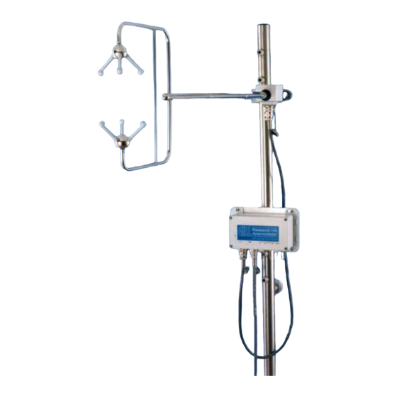
HS-50
Horizontally Symmetrical
Ultrasonic Research
Anemometer
User Manual
Doc No. 1199-PS-0032
Issue 02
Gill Instruments Ltd recognise all trademarks
Gill Instruments Limited
Saltmarsh Park,
67 Gosport Street,
Lymington,
Hampshire.
SO41 9EG
UK
Tel: +44 (0) 1590 613500
Fax: +44 (0) 1590 613501
E-mail: anem@gill.co.uk
Website: www.gill.co.uk
Advertisement
Table of Contents

Subscribe to Our Youtube Channel
Related Manuals for Gill Instruments HS-50


Summary of Contents for Gill Instruments HS-50
- Page 1 HS-50 Horizontally Symmetrical Ultrasonic Research Anemometer User Manual Doc No. 1199-PS-0032 Issue 02 Gill Instruments Ltd recognise all trademarks Gill Instruments Limited Saltmarsh Park, 67 Gosport Street, Lymington, Hampshire. SO41 9EG Tel: +44 (0) 1590 613500 Fax: +44 (0) 1590 613501 E-mail: anem@gill.co.uk...
- Page 3 Gill Instruments Ltd HS-50 Research Anemometer Page 1 Issue 02 Doc. No. 1199-PS-0032 November 2004...
-
Page 4: Table Of Contents
5.20 RCOM Error Messages......................20 5.21 Instructions For Using The Binary To ASCII Conversion Utility..........20 6. USING THE ANEMOMETER WITH A PC RUNNING RCOM II ..........22 6.1 PC Requirement..........................22 HS-50 Research Anemometer Page 2 Issue 02 Doc. No. 1199-PS-0032 November 2004... - Page 5 SUMMARY OF ABBREVIATIONS USED IN THIS MANUAL ..........51 PACKING LIST ..........................51 OPTIONAL EXTRAS........................51 APPENDIX B ............................52 Principle of Operation........................52 APPENDIX C ............................53 Sonic Temperature Measurement .....................53 APPENDIX D ............................60 Micro-Met Calculations........................60 APPENDIX E............................67 HS-50 Research Anemometer Page 3 Issue 02 Doc. No. 1199-PS-0032 November 2004...
-
Page 6: Hs-50 Research Anemometer
Gill Instruments Ltd RCOM Binary File Format .......................67 HS-50 Research Anemometer Page 4 Issue 02 Doc. No. 1199-PS-0032 November 2004... -
Page 7: Foreword
Gill Instruments Ltd 1. FOREWORD This manual refers to the Gill Instruments Ltd. Horizontally Symmetrical Research Ultrasonic Anemometer. It is an extremely sophisticated instrument and to achieve optimum performance we recommend that you read the whole of this manual before proceeding further with use. -
Page 8: System Installation
PCI should be earthed using the earth studs provided. 2.6 Cabling Ensure that strain relief measures are employed when installing the anemometer cables. Do not allow the whole weight of a cable to be applied to the connector. HS-50 Research Anemometer Page 6 Issue 02 Doc. No. 1199-PS-0032... -
Page 9: System Operation
These samples are block averaged before being converted into results. For wind speed, SoS and analogue inputs the number of samples used in the block average can be set to between 2 and 250 samples. The corresponding maximum number of PRT100 samples per result is 62. HS-50 Research Anemometer Page 7 Issue 02 Doc. -
Page 10: Wind Measurement, Sos And Temperature Reporting Format
3.10 Result Reporting The selected parameters are blocked together along with the diagnostic results and block control information to form a result message. The result message can either be in a Binary or ASCII format. HS-50 Research Anemometer Page 8 Issue 02 Doc. -
Page 11: Interactive Mode
3.13 Interrogation Commands Interrogation commands allow the user to request various information from the anemometer. HS-50 Research Anemometer Page 9 Issue 02 Doc. No. 1199-PS-0032... -
Page 12: Connection To A Pc Or Other Device
PCI. Baud rate options are: 2400 4800 9600 19200 38400 57600 115200 Data format: 1. 8 data, 1 stop, no parity. HS-50 Research Anemometer Page 10 Issue 02 Doc. No. 1199-PS-0032 November 2004... -
Page 13: Using The Anemometer With A Pc Running Rcom
COM3 or COM4, or if you have a non-standard COM1 or COM2.For example to instruct RCOM to seek an anemometer on COM3 using interrupt 4 the command would be: RCOM /C3 /CI4 HS-50 Research Anemometer Page 11 Issue 02 Doc. -
Page 14: Procedure If No Anemometer Is Found
If the anemometer is still not found then check that the settings of base address and interrupt vector are correct for your PC. If not use options 3 & 4 to correct them and option 1 to repeat the search for the anemometer. HS-50 Research Anemometer Page 12 Issue 02 Doc. -
Page 15: Main Menu
This allows the user to set various options. These are mostly to do with writing data to disk. (See Section 5.18) 5.12 Exit to DOS This quits the program and returns the user to the operating system. HS-50 Research Anemometer Page 13 Issue 02 Doc. No. 1199-PS-0032... -
Page 16: Trend Display
Pressing the “Alt” and “C” keys simultaneously (Alt-C) will clear the screen and start the data display from the left, with new scale values. Pressing the “Esc” key will stop any download that is in progress, terminate the display and return the user to the main menu. HS-50 Research Anemometer Page 14 Issue 02 Doc. -
Page 17: Display Micro-Met Parameters
‘Disp’ label is a tick then that parameter will be displayed on the micro-met parameters screen. If the entry under the ‘Log’ label is a tick then that parameter will be written to disk. HS-50 Research Anemometer Page 15 Issue 02 Doc. - Page 18 Von Karman Constant 0.40 Alp5Wcov X Specific Density of Air 1.225 Alp6Wcov X Specific Heat of Air 1004.67 Gravity Constant 9.80 Exit Sample Time (Minutes) Use Temperature Input Sonic Temp HS-50 Research Anemometer Page 16 Issue 02 Doc. No. 1199-PS-0032 November 2004...
-
Page 19: Tabular Display
+00.00 +00.00 -00.02 288.77 +00.01 +00.00 -00.01 288.75 +00.00 +00.00 -00.03 288.76 +00.00 +00.00 -00.02 288.77 +00.01 +00.00 -00.01 288.74 +00.00 +00.00 -00.02 288.75 -00.05 -00.39 -00.24 288.72 HS-50 Research Anemometer Page 17 Issue 02 Doc. No. 1199-PS-0032 November 2004... -
Page 20: Configure Anemometer
Channels enabled DDDDDD String Format BINARY Full Scale Deflect ASCII Terminator CRLF Direction Wrap Mode 360 Echo Message Mode Additional Features Confidence Tone DISABLED Axis Alignment AXIS EXIT HS-50 Research Anemometer Page 18 Issue 02 Doc. No. 1199-PS-0032 November 2004... -
Page 21: Options
All menu selections that set a parameter are stored in a data file on the hard disk in a file named “\RCOM\MICROMET.SET”. This prevents the users from having to re-enter settings each time the program is run. If this file cannot be found then default values will be used and the file created. HS-50 Research Anemometer Page 19 Issue 02 Doc. -
Page 22: Rcom Error Messages
100%, indicated by n). 5.21 Instructions For Using The Binary To ASCII Conversion Utility • Convert 3 is used with RCOM, the Solent R3, HS and HS-50 research anemometer PC software. • A binary file is converted to ASCII. • DOS command line options:- •... - Page 23 • Analogue inputs are output in volts to 4 decimal places. • If no selection of additional data is made then all the available data is converted. • A reminder of the above commands can be obtained by typing convert3 help. HS-50 Research Anemometer Page 21 Issue 02 Doc.
-
Page 24: Using The Anemometer With A Pc Running Rcom Ii
Select Start->Programs->RcomII 6.4 Using RCOM II RCOM II is a Windows program, which offers a simple terminal for viewing HS-50 output and or configuring the HS-50 using Interactive Mode. Refer to the Software Commands section for details on the Interactive Mode command set. -
Page 25: Using The Anemometer With A Pc Running Your Software
Wc 3 Ultrasonic axis 3 velocity in 0.01ms -1 units (Two's complement signed) Speed of Sound Field Speed of sound in 0.01ms -1 units (Unsigned) Speed Of Sound HS-50 Research Anemometer Page 23 Issue 02 Doc. No. 1199-PS-0032 November 2004... -
Page 26: Ascii Result Message Format
Ultrasonic axis 1 velocity in 0.01ms -1 units (±A 1 A 1 .A 1 A 1 ) Axis Speeds Wc 1 Ultrasonic axis 2 velocity in 0.01ms -1 units (±A 2 A 2 .A 2 A 2 ) Wc 2 HS-50 Research Anemometer Page 24 Issue 02 Doc. No. 1199-PS-0032... -
Page 27: Status Fields
If the error is caused by a memory or PRT failure, then after 16 consecutive failed readings, the error condition is reduced to the error code history status and the error cleared. StaD - Status Data Address 00 - Error codes Function HS-50 Research Anemometer Page 25 Issue 02 Doc. No. 1199-PS-0032 November 2004... - Page 28 Address 02 is repeated for 8 samples after a power on reset or exit from ‘Interactive Mode’ to allow the analogue output card or custom PC software to recognise the output configuration. Address 03 - Data output configuration 2 Bits 2,1,0 HS-50 Research Anemometer Page 26 Issue 02 Doc. No. 1199-PS-0032...
- Page 29 Channel pair 2 @ 90% Channel pair 2 @ 100% Bits 5,4 Channel pair 3 nominal Channel pair 3 @ 50% Channel pair 3 @ 90% Channel pair 3 @ 100% HS-50 Research Anemometer Page 27 Issue 02 Doc. No. 1199-PS-0032 November 2004...
-
Page 30: Software Commands
<BACKSPACE><SPACE><BACKSPACE>. The Escape Character The anemometer will respond to the <ESC> character by deleting all characters currently in it’s command buffer, and echo <TERM><TERM>. HS-50 Research Anemometer Page 28 Issue 02 Doc. No. 1199-PS-0032... - Page 31 Description: Sets the wind measurement reporting format. Parameters: UVW Reports wind velocity in UVW format. POLAR Reports wind velocity in polar + W format. AXIS Reports wind as axis velocities. Wind results are calibrated. HS-50 Research Anemometer Page 29 Issue 02 Doc. No. 1199-PS-0032 November 2004...
- Page 32 ASCII fields unpadded. ASCTERM Syntax: ASCTERM CR | CRLF Description: Sets ASCII output string terminator. Parameters: ASCII output string terminator is <CR>. CRLF ASCII output string terminator is <CR><LF>. HS-50 Research Anemometer Page 30 Issue 02 Doc. No. 1199-PS-0032 November 2004...
- Page 33 Description: Reports a brief description of all the available commands. Syntax: HELP command Description: Reports a description of the command requested. Syntax: Description: Reports the anemometer’s serial number. Syntax: Description: Reports the anemometer’s software version. HS-50 Research Anemometer Page 31 Issue 02 Doc. No. 1199-PS-0032 November 2004...
-
Page 34: Doc. No. 1199-Ps
Description: Selects UVW alignment from two alternative definitions Parameters: AXIS Aligns the U axis to transducer axis 1 when viewed from above. SPAR Aligns the U axis with the main spar. HS-50 Research Anemometer Page 32 Issue 02 Doc. No. 1199-PS-0032... -
Page 35: Using The Analogue Inputs Of The Anemometer
Analogue input 1+ / 3+ / 5+ Analogue ground Analogue input 1- / 3- / 5- Analogue input 2+ / 4+ / 6+ Analogue input 2- / 4- / 6- Sensor power + Chassis/screen HS-50 Research Anemometer Page 33 Issue 02 Doc. No. 1199-PS-0032 November 2004... -
Page 36: Using The Prt Input
PRT excitation + PRT sense + PRT 100 PRT sense - PRT excitation - For correct operation the PRT connections must be isolated from the rest of the system. HS-50 Research Anemometer Page 34 Issue 02 Doc. No. 1199-PS-0032 November 2004... -
Page 37: Using The Analogue Outputs
The voltage output at a given temperature is independent of the anemometer's temperature output configuration. The following table shows the mapping between voltage and temperature: Output voltage (V) -1.667 +2.5 HS-50 Research Anemometer Page 35 Issue 02 Doc. No. 1199-PS-0032 November 2004... -
Page 38: Analogue Sync. Output
0.00v. i.e. the sequence is first output on channel 1, then channel 2, then 3 etc. For this test the complete sequence lasts 160 seconds. HS-50 Research Anemometer Page 36 Issue 02 Doc. -
Page 39: Drawings
Gill Instruments Ltd 11. DRAWINGS HS-50 Research Anemometer Page 37 Issue 02 Doc. No. 1199-PS-0032 November 2004... -
Page 40: 1086-M-043 Anemometer Cable(Voltage Out)
Gill Instruments Ltd 1086-M-043 Anemometer Cable(Voltage Out) HS-50 Research Anemometer Page 38 Issue 02 Doc. No. 1199-PS-0032 November 2004... -
Page 41: 1189-K-022 Indoor Pci Unit Dimensions
Gill Instruments Ltd 1189-K-022 Indoor PCI Unit Dimensions HS-50 Research Anemometer Page 39 Issue 02 Doc. No. 1199-PS-0032 November 2004... -
Page 42: 1199-K-066 3 Axis Horizontal Anemometer U,V &W Axis Definitions
Gill Instruments Ltd 1199-K-066 3 Axis Horizontal Anemometer U,V &W Axis Definitions HS-50 Research Anemometer Page 40 Issue 02 Doc. No. 1199-PS-0032 November 2004... -
Page 43: 1199-K-089 3 Axis Horizontal Anemometer Head + Electronics Mounting Details
Gill Instruments Ltd 1199-K-089 3 Axis Horizontal Anemometer Head + Electronics Mounting Details HS-50 Research Anemometer Page 41 Issue 02 Doc. No. 1199-PS-0032 November 2004... -
Page 44: 1210-K-068 R3 & Hs Research Anemometer Measurement Sequence
1. L → U indicates lower to upper transducer firing U → L indicates upper to lower transducer firing 2. Serial output of the previous measurement commences as SYNC goes high HS-50 Research Anemometer Page 42 Issue 02 Doc. No. 1199-PS-0032... -
Page 45: Assembly Of Amphenol C91A Screw Lock 4 Way Socket
Gill Instruments Ltd Assembly of Amphenol C91A Screw Lock 4 Way Socket HS-50 Research Anemometer Page 43 Issue 02 Doc. No. 1199-PS-0032 November 2004... -
Page 46: Technical Specification
<150mA for 24Vdc input 12.5 Serial Interface Electrical Interface: Full Duplex RS422 Baud Rates: 2400, 4800, 9600, 19200, 38400, 57600, 115200 Format: 8 data, 1 stop bit, No parity HS-50 Research Anemometer Page 44 Issue 02 Doc. No. 1199-PS-0032 November 2004... -
Page 47: Analogue Inputs
RS422RXA (Data to anemometer) Supply V+ Reserved Reserved Chassis Anemometer Sync- Not used Not used Digital 0V, signal ground Supply V- Reserved Reserved Reserved Anemometer Sync + Reserved Reserved HS-50 Research Anemometer Page 45 Issue 02 Doc. No. 1199-PS-0032 November 2004... -
Page 48: Power And Communications Interface
Not used Not used Not used RS232 connector 9 way D type socket Designation RXD (data from anemometer to PC) TXD (data from PC to anemometer) Signal Ground HS-50 Research Anemometer Page 46 Issue 02 Doc. No. 1199-PS-0032 November 2004... - Page 49 Note: The above termination is for when the receive circuit is floating relative to the anemometer. If the receive circuit is referred to Anemometer Signal Ground or Anemometer Supply - then the earth connection marked 'e' should be omitted. HS-50 Research Anemometer Page 47 Issue 02 Doc.
-
Page 50: Pci Specification
+3V to +5V (referred to signal ground) <1V Output resistance: <100Ω, short circuit proof Load resistance: Greater than 10kΩ Load capacitance: Between 0 and 1000pF (e.g. 10m of coax) HS-50 Research Anemometer Page 48 Issue 02 Doc. No. 1199-PS-0032 November 2004... - Page 51 Gill Instruments Ltd Test 1, Test 2 Inputs Logic high (inactive) +3V to +5V or open circuit Logic low (active) <1V The above voltages are referenced to signal ground. HS-50 Research Anemometer Page 49 Issue 02 Doc. No. 1199-PS-0032 November 2004...
-
Page 52: Summary Of Abbreviations Used In This Manual
Electronics Unit Platinum Resistance Thermometer RS232 Communications standard RS422 Communications standard Speed of Sound RCOM Gill Instruments Ltd. PC communications software PACKING LIST HS-50 anemometer, comprising: • Head • Electronics Unit • 1.5m interconnecting cable • Case • RCOM software •... -
Page 53: Principle Of Operation
Standard vector mathematics leads to the following equations:- U velocity = (2a1 - a2 - a3)/1.9779 V velocity = (a3 - a2 )/1.1420 W velocity = (a1 + a2 + a3)/2.2555 HS-50 Research Anemometer Page 51 Issue 02 Doc. No. 1199-PS-0032... -
Page 54: Sonic Temperature Measurement
Gill Instruments Ltd APPENDIX C Sonic Temperature Measurement HS-50 Research Anemometer Page 52 Issue 02 Doc. No. 1199-PS-0032 November 2004... -
Page 55: Doc. No. 1199-Ps-0032 November
Gill Instruments Ltd HS-50 Research Anemometer Page 53 Issue 02 Doc. No. 1199-PS-0032 November 2004... - Page 56 Gill Instruments Ltd HS-50 Research Anemometer Page 54 Issue 02 Doc. No. 1199-PS-0032 November 2004...
- Page 57 Gill Instruments Ltd HS-50 Research Anemometer Page 55 Issue 02 Doc. No. 1199-PS-0032 November 2004...
- Page 58 Gill Instruments Ltd HS-50 Research Anemometer Page 56 Issue 02 Doc. No. 1199-PS-0032 November 2004...
- Page 59 Gill Instruments Ltd HS-50 Research Anemometer Page 57 Issue 02 Doc. No. 1199-PS-0032 November 2004...
- Page 60 Gill Instruments Ltd HS-50 Research Anemometer Page 58 Issue 02 Doc. No. 1199-PS-0032 November 2004...
-
Page 61: Micro-Met Calculations
Gill Instruments Ltd APPENDIX D Micro-Met Calculations HS-50 Research Anemometer Page 59 Issue 02 Doc. No. 1199-PS-0032 November 2004... - Page 62 Gill Instruments Ltd HS-50 Research Anemometer Page 60 Issue 02 Doc. No. 1199-PS-0032 November 2004...
- Page 63 Gill Instruments Ltd HS-50 Research Anemometer Page 61 Issue 02 Doc. No. 1199-PS-0032 November 2004...
- Page 64 Gill Instruments Ltd HS-50 Research Anemometer Page 62 Issue 02 Doc. No. 1199-PS-0032 November 2004...
- Page 65 Gill Instruments Ltd HS-50 Research Anemometer Page 63 Issue 02 Doc. No. 1199-PS-0032 November 2004...
- Page 66 Gill Instruments Ltd HS-50 Research Anemometer Page 64 Issue 02 Doc. No. 1199-PS-0032 November 2004...
- Page 67 0=10m/s, 1= 20m/s, 2= 30m/s, 3= 60m/s analogue_output_wrap unsigned char 0 = 360°, 1= 540° file create time unsigned long file create time in seconds since 00:00:00 GMT, January 1970 2. Binary Data HS-50 Research Anemometer Page 65 Issue 02 Doc. No. 1199-PS-0032 November 2004...
- Page 68 ” analogue input 4 long ” analogue input 5 long ” analogue input 6 long ” clino_x short int in 0.01° increments clino_y short int in 0.01° increments HS-50 Research Anemometer Page 66 Issue 02 Doc. No. 1199-PS-0032 November 2004...
- Page 69 If the anemometer output string format is binary then analogue inputs are stored in the binary file as follows:- Voltage Analogue Input Value + 4.9994 8191 0.0000 0000 - 5.0000 -8192 HS-50 Research Anemometer Page 67 Issue 02 Doc. No. 1199-PS-0032 November 2004...
Need help?
Do you have a question about the HS-50 and is the answer not in the manual?
Questions and answers