Advertisement
INSTRUCTION MANUAL
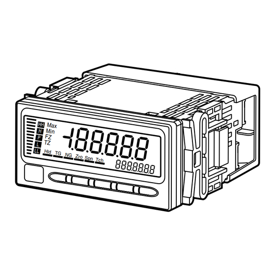
RTD INPUT DIGITAL PANEL METER
(5 digit, LCD display type)
BEFORE USE ....
Thank you for choosing us. Before use, please check con-
tents of the package you received as outlined below.
If you have any problems or questions with the product,
please contact our sales office or representatives.
■ PACKAGE INCLUDES:
Digital panel meter
(body + mounting bracket × 2 + watertight packing) ........(1)
Engineering unit sticker label sheet ..................................(1)
■ MODEL NO.
Confirm Model No. marking on the product to be exactly
what you ordered.
■ INSTRUCTION MANUAL
This manual describes necessary points of caution when
you use this product, including installation, connection and
basic maintenance procedures.
For detailed explanations to operate and program the mod-
ule, please refer to Model 47DR Operating Manual (EM-
9509-B).
The 47D Series is programmable either by using the front
control buttons or the PC Configurator Software. For de-
tailed information on the PC configuration, refer to the
47DCFG users manual.
Software and manuals are downloadable at our web site.
POINTS OF CAUTION
■ POWER INPUT RATING & OPERATIONAL RANGE
• Locate the power input rating marked on the product and
confirm its operational range as indicated below:
100 – 240V AC rating: 85 – 264V, 50/60 Hz, ≤ 12VA
24V DC rating: 24V ±10%, ≤ 3.5W
110V DC rating: 85 – 150V, ≤ 3.5W
■ GENERAL PRECAUTIONS
• Before you remove the unit or mount it, turn off the power
supply and input signal for safety.
• Be sure to put the terminal cover on while the power is
supplied.
■ ENVIRONMENT
• Indoor use.
• When heavy dust or metal particles are present in the
air, install the unit inside proper housing with sufficient
ventilation.
• Do not install the unit where it is subjected to continuous
vibration. Do not subject the unit to physical impact.
• Environmental temperature must be within -10 to +55°C
(14 to 131°F) with relative humidity within 30 to 90% RH
in order to ensure adequate life span and operation.
• Be sure that the ventilation slits are not covered with ca-
bles, etc.
MG CO., LTD. www.mgco.jp
5-2-55 Minamitsumori, Nishinari-ku, Osaka 557-0063 JAPAN
MODEL
■ REQUIREMENTS TO ENSURE IP66
• Observe the designated panel cutout size (W92 × H45
mm).
• The watertight packing included in the product package
must be placed behind the front cover.
• Both mounting brackets must be fastened tightly until
they hit the panel.
• Confirm visually that the packing is not contorted or ex-
cessively run off the edge after installation.
■ WIRING
• Make sure for safety that only qualified personnel per-
form the wiring.
• Do not install cables close to noise sources (high frequen-
cy line, etc.).
• Do not bind these cables together with those in which
noises are present. Do not install them in the same duct.
■ TERMINAL BLOCK
• How to remove the terminal cover
Insert the minus tip of a screwdriver into each hole at the
four corners of the cover and pull it to the direction as
indicated below to separate the terminal cover.
• How to remove the terminal block
The terminal block is separable in two pieces. Loosen two
screws on both sides of the terminal block to separate.
Be sure to turn off the power supply, input signal and
power supply to the output relays before separating the
terminal block.
47DR
Terminal Cover
Terminal Block
Separable
Terminal Block
Screw
EM-9509-A Rev.6 P. 1 / 8
Advertisement
Table of Contents

Related Manuals for MG 47DR


Summary of Contents for MG 47DR
- Page 1 Insert the minus tip of a screwdriver into each hole at the For detailed explanations to operate and program the mod- four corners of the cover and pull it to the direction as ule, please refer to Model 47DR Operating Manual (EM- indicated below to separate the terminal cover. 9509-B).
-
Page 2: Lightning Surge Protection
Panel Watertight packing Mounting Bracket min. 120 Panel thickness: 1.6 to 8.0 mm EM-9509-A Rev.6 P. 2 / 8 MG CO., LTD. www.mgco.jp 5-2-55 Minamitsumori, Nishinari-ku, Osaka 557-0063 JAPAN... -
Page 3: Component Identification
Used to move on to the setting standby status and shift through display digits in each setting item. (12) Up button Used to change setting values. Note: Refer to the operating manual for details on each function. EM-9509-A Rev.6 P. 3 / 8 MG CO., LTD. www.mgco.jp 5-2-55 Minamitsumori, Nishinari-ku, Osaka 557-0063 JAPAN... -
Page 4: Terminal Connections
14 15 16 1.25 mm , stripped length 7 – 8 mm) EURO TYPE BCD output: 50-pin connector 50-pin CONNECTOR CONNECTOR TERMINAL (Honda Tsushin Kogyo HDR-E50LFDT1-SLE+) EM-9509-A Rev.6 P. 4 / 8 MG CO., LTD. www.mgco.jp 5-2-55 Minamitsumori, Nishinari-ku, Osaka 557-0063 JAPAN... - Page 5 DO NOT SHORT across the terminals 1 / 2 / 3 and 5 / 6. Two-wire Transmitter +12V +24V SENSOR 4 – 20mA DC – – – RECEIV. INSTR. EM-9509-A Rev.6 P. 5 / 8 MG CO., LTD. www.mgco.jp 5-2-55 Minamitsumori, Nishinari-ku, Osaka 557-0063 JAPAN...
- Page 6 (when there is no cross-wiring), close across the terminal 12 – 13 with a leadwire. When the device is not at the end, no shortcircuit wire is required. EM-9509-A Rev.6 P. 6 / 8 MG CO., LTD. www.mgco.jp 5-2-55 Minamitsumori, Nishinari-ku, Osaka 557-0063 JAPAN...
- Page 7 RESET : 14 ZERO : 15 HOLD Hc, HHc 2 kΩ RESET 1.5 kΩ L OUTPUT open ZERO contact collector LL OUTPUT Lc, LLc EM-9509-A Rev.6 P. 7 / 8 MG CO., LTD. www.mgco.jp 5-2-55 Minamitsumori, Nishinari-ku, Osaka 557-0063 JAPAN...
-
Page 8: System Configuration Examples
MDP-4R) * Digital Panel Meter Digital Panel Meter (model: 47Dx) (model: 47Dx) *1. Insert lightning surge protectors recommended in this example if necessary. EM-9509-A Rev.6 P. 8 / 8 MG CO., LTD. www.mgco.jp 5-2-55 Minamitsumori, Nishinari-ku, Osaka 557-0063 JAPAN...
Need help?
Do you have a question about the 47DR and is the answer not in the manual?
Questions and answers