
Related Manuals for CAME CAT1DAGS


Summary of Contents for CAME CAT1DAGS
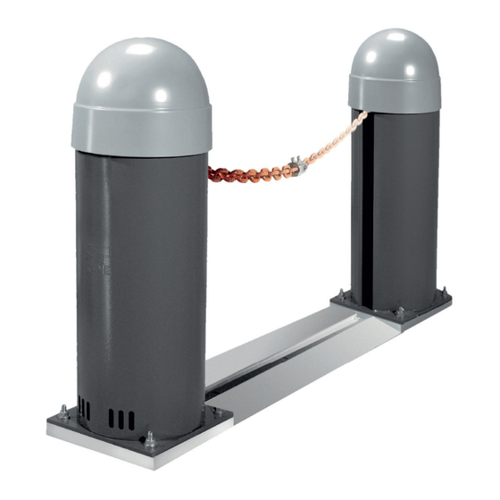
- Page 1 Chain barriers FA01928-EN CAT1DAGS CAT2NNGS CAT1DACS CAT2NNCS Italiano INSTALLATION MANUAL...
- Page 2 DEVICE MANUAL RELEASE With the gearmotor released, the operator does not work. CAT1DAGS CAT1DACS CAT1DAGS CAT1DACS...
- Page 3 (railway carriage, containers, closed vehicles). • If the product malfunctions, stop using it and contact an authorised support centre. The manufacture date is provided in the production batch printed on the product label. If necessary, contact us at https://www. came.com/global/en/contact-us. The general conditions of sale are given in the official CAME price lists.
-
Page 4: Dismantling And Disposal
DISMANTLING AND DISPOSAL CAME S.p.A. employs an Environmental Management System at its premises. This system is certified and compliant with the UNI EN ISO 14001 standard to ensure that the environment is respected and safeguarded. Please continue safeguarding the environment. At CAME we consider it one of the fundamentals of our operating and market strategies. - Page 5 (**) The average product life specified should be understood purely as an indicative estimate. It applies to normal usage conditions and where the product has been installed and maintained in compliance with the instructions provided in the CAME technical manual. The average product life is also affected, including significantly,...
- Page 6 Fuse table MODELS CAT1DAGS CAT1DACS Line fuse 2 A-F 2 A-F Accessory fuse 2 A-F 2 A-F Description of parts Barrier Countersunk screw M12x30 Counterweight Chain fastening lock Dome Limit-switch assembly Casing Limit-switch assembly guard Control panel Lock for release...
-
Page 7: Control Board
Control board Terminal board for motor power supply RSE card connector Terminal board for connecting the limit switches Programming buttons Terminal board for connecting the safety devices Terminal board for CRP connection Terminal board for connecting control devices Terminal board for connecting the keypad selector Terminal board for connecting the antenna Terminal board for connecting the transponder selector switch Connector for plug-in radio frequency card (AF) - Page 8 Size CAT1DAGS CAT2NNGS CAT1DACS CAT2NNCS max 8000 (001CAT-5) max 16000 (001CAT-15) Cable types and minimum thicknesses Cable length (m) up to 20 from 20 to 30 Power supply 230 V AC 3G x 1.5 mm² 3G x 2.5 mm² 24 V AC/DC flashing beacon 2 x 1 mm²...
-
Page 9: Installation
Dig a hole for the foundation frame. Set up the corrugated tubes needed for the wiring coming out of the junction pit. The number of tubes depends on the type of system and the accessories that are going to be fitted. CAT1DAGS CAT1DACS CAT2NNGS CAT2NNCS Dig a hole for the below-ground chain protection track (CAR-4). - Page 10 Laying the anchoring plate Set up a foundation frame that is larger than the anchoring plate. Insert the foundation frame into the dug hole. If the above-ground track is used (001CAR-2), the foundation frame must protrude 50 mm above ground level. Fit an iron cage in the foundation frame to reinforce the concrete.
- Page 11 Fixing the pillars and chain protection track Place the pillars on top of the anchoring plates and secure them using washers and nuts. CAT1DAGS CAT1DACS CAT2NNGS CAT2NNCS Remove the domes by unscrewing the screws. CAT1DAGS CAT1DACS CAT2NNGS CAT2NNCS...
- Page 12 Remove the pillar casing (CAT1DAGS / CAT1DACS). Release the chain in the pillar (CAT2NNGS / CAT2NNCS) by removing the tie. CAT1DAGS CAT1DACS CAT2NNGS CAT2NNCS Lay the chain protection track between the two pillars. Cut off any excess. CAT1DAGS CAT1DACS CAR-2...
- Page 13 Calculate the length of barrier chain required and cut off the excess. CAT1DAGS CAT1DACS CAT2NNGS CAT2NNCS Fasten the barrier chain to the CAT1DAGS / CAT1DACS service chain using the fastening terminal. Secure the other end to the CAT2NNGS / CAT2NNGS service chain using the lock. CAT1DAGS CAT1DACS CAT2NNGS CAT2NNCS All operational checks and final testing must be performed once the system is complete and the chain has been installed.
-
Page 14: Limit-Switch Assembly
Limit-switch assembly Opening micro limit switch Closing micro limit switch Cam for setting the opening travel end point Cam for setting the closing travel end point CAT1DAGS CAT1DACS CAT2NNGS CAT2NNCS Opening limit-switch By default, the opening microswitch is already activated by the open limit switch cam. - Page 15 Closing safety limit switch The closing microswitch is used to stop the operator safely, should the chain break. With the control panel powered, send a closing command and wait for the gearmotor to stop (amperometric sensitivity). With the gearmotor stopped, position the close limit switch cam near the closing microswitch without activating it as shown.
-
Page 16: Electrical Connections
Passing the electrical cables The electrical cables must not touch any parts that may overheat during use (such as the motor and transformer). Make sure that the moving mechanical parts are suitably far away from the wiring. CAT1DAGS CAT1DACS Power supply Make sure the mains power supply is disconnected during all installation procedures. - Page 17 Maximum capacity of contacts The total power of the outputs listed below must not exceed the maximum output power [Accessories] Device Output Power supply (V) Power (W) Accessories 10-11 24 AC Additional light 10-E 24 AC Flashing beacon 10-E 24 AC Operator status warning light 10 - 5 24 AC...
-
Page 18: Signalling Devices
Signalling devices Additional light It increases the light in the manoeuvring area. See function [F18 - Additional light]. Additional flashing beacon It flashes when the operator opens and closes. Operator status warning light It notifies the user of the operator status. See function [F10 - Passage-open warning light]. - Page 19 Photocells Connect the safety devices to the CY input (NC contacts). During programming, configure the type of action that must be performed by the device connected to the input. If the CY contact is used, it must be configured during programming. For systems with multiple pairs of photocells, please see the manual for the relevant accessory.
-
Page 20: Functions Menu
PROGRAMMING Programming button functions ESC button The ESC button is used to perform the operations described below. Exit the menu Delete the changes Go back to the previous screen < > buttons The <> buttons are used to perform the operations described below. Navigate the menu Increase or decrease values ENTER button... - Page 21 Obstacle with motor stopped With the function active and the operator stopped, an open or close command is not performed if the safety devices detect an obstacle. The function is active when the passage is closed or open, or after a complete stop. OFF (Default) Open warning light It notifies the user of the operator status.
- Page 22 Save data Save user data, timings and configurations to the memory device (memory roll). The function is displayed only when a memory roll card is inserted into the control board. OFF (Default) ON (Run operation) Read data Upload user data, timings and configurations to the memory device (memory roll). The function is displayed only when a memory roll card is inserted into the control board.
-
Page 23: Import/Export Data
Remove all Remove all registered users. OFF (Default) Radio decoding Choose the type of radio coding for the transmitters enabled to control the operator. If you choose the type of radio coding for the transmitters [Rolling code] or [TW key block], any transmitters with a different type of radio coding saved previously will be deleted. -
Page 24: Final Operations
FINAL OPERATIONS CAT1DAGS CAT1DACS CAT2NNGS CAT2NNCS CAT1DAGS CAT1DACS CAT2NNGS CAT2NNCS... - Page 25 MCBF Models Chain 9 mm 8 m 50.000 Chain 5 mm 16 m -10% The MCBF value relates to the barrier only and does not refer to any applicable accessories. Before carrying out any cleaning or maintenance, or replacing any parts, disconnect the device from the power supply. This document informs the installer of the checks that must be carried out during maintenance.
-
Page 26: Error Messages
ERROR MESSAGES Service test failure error The maximum number of obstacles detected consecutively has been exceeded Limit switch input error or both limit switches open Incompatible transmitter error NOTICES Wire contact 1-2 (NC) is open. Wire contact 2-CX (NC) is open. C1, C4, C5 The photocell wire contact 2-CY (NC) is open. - Page 28 AFFIX THE PRODUCT LABEL FROM THE BOX HERE CAME S.p.A. Via Martiri della Libertà, 15 31030 Dosson di Casier Treviso – Italy Tel. (+39) 0422 4940 Fax (+39) 0422 4941...
Need help?
Do you have a question about the CAT1DAGS and is the answer not in the manual?
Questions and answers