Table of Contents
Advertisement
Quick Links
No.SK00-8202-SI-120-00
Deposition Controller
Instruction Manual
CRTM series
Quartz Crystal Deposition Controller
CRTM-R1
This instruction manual is intended for products with the
following serial numbers and later:
S/N 0001~
Be sure to read this manual before using this product.
Keep it with care to use it at any time.
ULVAC,Inc. Components Division
https://www.ulvac.co.jp/
I
Advertisement
Table of Contents

Related Manuals for Ulvac CRTM Series


Summary of Contents for Ulvac CRTM Series
- Page 1 No.SK00-8202-SI-120-00 Deposition Controller Instruction Manual CRTM series Quartz Crystal Deposition Controller CRTM-R1 This instruction manual is intended for products with the following serial numbers and later: S/N 0001~ Be sure to read this manual before using this product. Keep it with care to use it at any time.
- Page 2 All copyright of this instruction manual belongs to ULVAC, Inc. Any part of this instruction manual must not be copied without our permission.
- Page 3 Failure to do so may cause fire or electric shock. For your safety, please contact the supplier, the network listed in this manual, or the Components division of ULVAC, Inc. for repair. Power off When replacing the fuse, be sure to turn off the power switch and WARNING unplug the power plug.
- Page 4 Check Wiring WARNING Make sure that the wiring is correct before turning on the power. Incorrect wiring may cause damage or fire. Check power supply voltage Before turning on the power supply, make sure that the operating WARNING voltage of the deposition controller and the supply voltage are the same.
- Page 5 Disposal When disposing of the ULVAC product, comply with the local regulations. Especially if the sensor is used in an atmosphere that CAUTION may cause a danger to humans, use a specialized disposal company to dispose of it. Please note that customers are responsible for all disposal costs.
- Page 6 Revision History Date Revision Reason Number 4/1/2022 First edition...
-
Page 7: Table Of Contents
CRTM-R1 ....5 Specifications ...... 26 CTM(-D) ....8 5.4. RS-232C Communication 3.3. Sensors ....... 10 specifications ...... 27 Types of ULVAC Sensors ..10 5.5. LAN(Ethernet)Communication Cooling Water Standard for specifications ...... 27 ULVAC Sensors ..... 13 6. Program ......28 3.4. - Page 8 6.3.2.5.3. Calc-Z ....47 Material Table Edit ..81 6.3.2.5.4. Calc Thickness Mode . 47 7. File Manager ...... 82 Process Program ... 48 7.1. Program Manager ....83 Process Program Copy .. 49 File Operation .... 84 Depo Program ....50 USB >...
- Page 9 Description of Functions ..135 Request for System Parameter 108 12.1. Film Thickness Measurement ... 135 Request for Depo Program .. 109 12.2. Deposition sequence ..136 Request for Process Program 110 12.3. Upper Jump/Lower Jump ..136 Batch request for System 12.4.
-
Page 10: Overview
Overview CRTM-R1 is a crystal deposition controller developed based on the technology ULVAC has cultivated over many years. By adopting a new measurement method, it achieves rate stability and higher resolution than conventional models. It can be used for a wide range of vapor deposition processes, from metal films to optical films. -
Page 11: Standard Specifications
Standard specifications Table 1. CRTM-R1 Standard specifications, Performance specifications Frequency Measurement range 4.00 to 3.00MHz @4MHz 5.00 to 3.50MHz @5MHz 6.00 to 4.50MHz @6MHz Measurement resolution 1mHz Display resolution 1mHz Deposition rate Measurement range *1 0.000 to 999.9Å/s (0 to 99.99nm/s) Measurement resolution *2 0.0028Å/s @4MHz 0.0018Å/s @5MHz... - Page 12 CTM:Approx, 80×152×53 mm CRTM-R1:5.3kg (up to 5.8kg with Weight kg options installed) CTM:0.6 kg Utility AC 100 to 240V±10% , 50/60Hz Maximum Power Consumption 150W Suitable Fuse 250V 2.5A (2pcs of 5×20mm) IP Protection Class IP20 Overvoltage Category CAT.Ⅱ Altitude 2000m or less above sea level Pollution level Temperature 5 to 40℃...
-
Page 13: Equipment Configuration And External View
Equipment Configuration and External view 3.1. Equipment Configuration 〇 Standard items ・ CRTM-R1(1 IF card and 1 DIO card are included) 1 set ・ Power cable (3m) 1 pc ・ Instruction manual CD 1 set 〇 Options ・ IF card: Up to four cards can be installed. ・... -
Page 14: External View
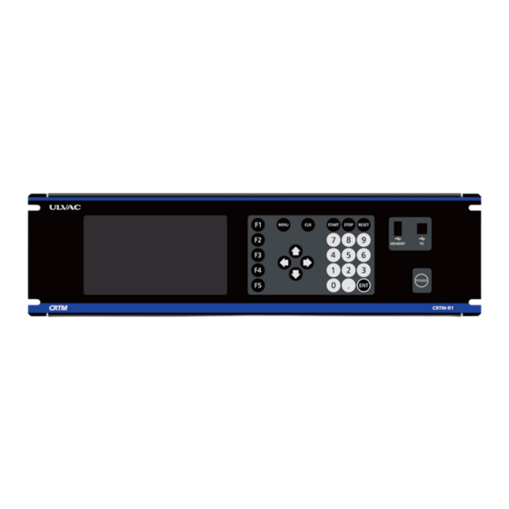
3.2. External view CRTM-R1 Figure 2. CRTM-R1 External dimensions. Figure 3. CRTM-R1 Front view of the main unit. - Page 15 ① POWER Switch POWER switch of CRTM-R1 Note that the power does not turn ON unless the power switch on the rear panel is turned ON before turning on this power switch. The LEDs on the switch indicate the CRTM-R1 in the following states. No lighting :No electricity (switch on the back is OFF) Lights orange...
- Page 16 ② ④ ⑥ ⑦ ⑧ ⑨ ① ③ ⑤ Figure 4. CRTM-R1 Rear view of the main unit. ① Power input terminal Terminal to plug in the power cable. Fuses can be replaced here. ② Power switch Power switch of CRTM-R1.If this switch is not ON, the power does not turn on even if the switch on the front is turned on.
-
Page 17: Ctm(-D)
CTM(-D) Figure 5. CTM External dimensions. Figure 6. CTM-D External dimensions. ② ① ⑥ ⑦ ④ ③ ⑤ ⑧ ⑨ Figure 7. CTM(-D) Front view Figure 8. CTM Rear view Figure 9. CTM-D Rear view ① Power switch Power switch of CTM(-D). ②... - Page 18 FAIL It lights up when an error occurs. TRACK It blinks while the quartz crystal plate is searching the resonance point. It lights up when the quartz crystal plate completes the resonance point search and the track operation starts. READY It lights up after CTM turns on and is ready for operation.
-
Page 19: Sensors
3.3. Sensors Types of ULVAC Sensors Sensors for CRTM series wide variety of products are available for use in various deposition systems. Please select a sensor from the table below according to the application. Table 3.Sensor Type Sensor Type Sensor Name... - Page 20 Figure 11. Assembly of water-cooled jacket and CRTS-0 Figure 12. CRTS-4,6 type, with φ30 feedthrough terminal Figure 13. CRTS-4,6 with ICF70 flange Figure 14. CRTS-4U,6U type with ICF70 flange Figure 15. Multi-sensor CRTS-12NS sensor head...
- Page 21 Figure 16 Multi-sensor CRTS-M6 sensor head...
-
Page 22: Cooling Water Standard For Ulvac Sensors
Cooling Water Standard for ULVAC Sensors Refer to the table below for cooling water standards. Table 5 Water quality standards for Cooling water Item Reference value Visual Turbidity 3 or less [Degree (Kaolin)] Specific resistance 5 kΩ・cm or more (25 °C) Langelier index -0.5 to 0.5... -
Page 23: Types Of Quartz Crystal Plates And Precautions
3.4. Types of Quartz Crystal Plates and Precautions There are two electrode materials for ULVAC quartz crystal plates: gold (UCR-5MAU-12, UCR-6MAU) and silver (UCR-5MAG-12, UCR-4MAG-12). Regardless of the electrode film type, the basic oscillation frequencies are 4MHz, 5MHz and 6MHz.These are used depending on the deposition materials and deposition atmosphere (corrosive gas). -
Page 24: Cable
3.5. Cable ・ Vacuum inner cable A cable to connect the sensor head to the OSM connector of the flange or the feedthrough terminal. Select the suitable length from 0.2m, 0.5m, 0.9m, 1.5m, 3.0m.. The single sensor with a water-cooling pipe has a maximum length of 800mm, so it is not recommended to use 1.5m or 3.0m. -
Page 25: Preparation
Preparation 4.1. Mounting on rack Mounting on rack To mount CRTM-R1 on a 19-inch rack, remove its rubber feet. Pull the rubber feet with a tool such as tweezers to remove them. The depth of the rack should be at least 400mm to allow for cable connections through the rear panel. -
Page 26: Wiring Of If Card
The figure above is a general installation example and does not CAUTION necessarily guarantee that all devices can be measured. Use ULVAC products for sensors, CTMs, cables, and others for CRTM-R1. Please note that customers are responsible for the operation when CAUTION using CRTM-R1 with non-ULVAC products installed. -
Page 27: Wiring Of Dio Card
① Sensor Input Signal Connect the CTM(-D) and the sensor head to CTM1 and CTM2. For the optional cards, connect the CTM and sensor head to CTM3, CTM4, …CTM8, in the same way. Figure 24 shows how to connect them. External cable for CTM Vacuum inner cable Auxiliary cable 0.5m... -
Page 28: Wiring For Ao Card
4.6. Wiring for AO Card The AO card is not included as standard, and up to one additional DIO cards can be installed as an option. Connect the mini D-Sub15 female connector cable. Deposition rate, film thickness and power output of each CTM are output as analog signals. The full scale is set in 6.3.4. -
Page 29: Precautions Before Use
the red frame on the back of the main unit. Figure 289. Insertion port of LAN cable on the back ③ USB2.0 Type-B When using USB2.0 Type-B for external communication, connect a USB cable with a male B- type connector to the port in the red frame on the front of the main unit. ※... -
Page 30: Flow Of Crtm-R1 Use
Turn on the power switch on the back panel, and then turn on the POWER switch on the front panel. *After pressing the power switch on the front panel, the ULVAC logo appears on display, then the light turns off. This is not a malfunction. - Page 31 ⑥ External Control Set this setting when controlling this unit from the deposition Settings system control circuit. Refer to 6.3.5. Digital Input Port Program. Set this setting when sending the status of this unit to the deposition system control circuit. Refer to 6.3.6 Digital Output Port Program.
-
Page 32: Signal Specifications
Signal Specifications 5.1. Analog Output(AO) Specifications IF Card Analog Output(AO-1~AO-8) Resolution 16bit Output Range -10V~+10V Single-ended output Connector BNC female connector * The figure shows when the maximum number of optional cards are installed. Figure 31 AO Connector ⇐ ⇒ CRTM-R1 EXTERNAL 50Ω... - Page 33 AO-11 AO-14 AO-12 AO-13 AO-15 AO-16 * The figure shows when the maximum number of optional cards are installed. Figure 33. AO connector ⇐ ⇒ CRTM-R1 EXTERNAL 50Ω LOAD ±10V, BNC-Shell ≦20mA Figure 34. Example of AO Wiring...
-
Page 34: Digital Input (Di) Specifications
5.2. Digital Input (DI) Specifications Specifications Photocoupler-isolated input Maximum applied voltage: 24VDC TTL level input specification (High(min):2.5V, Low(max): 1.1V) Connector D-Sub15 male (Fitting with inch screw #4-40UNC) Table8. DI Port Port No. Signal Name Port No. Signal Name DI-COM DI-7 DI-14 DI-6 DI-13... -
Page 35: Digital Output (Do) Specifications
5.3. Digital Output (DO) Specifications Specifications Optical relay output (Maximum rating: 60VAC, 500mA Recommended operating conditions: 48V, 500mA), individually isolated. Connector D-Sub25 male (Fitting with inch screw #4-40UNC) Table 9 DO Port Port No. Signal Name Port No. Signal Name DO-7 DO-7COM DO-6... -
Page 36: Rs-232C Communication Specifications
5.4. RS-232C Communication specifications Specifications Comply with RS-232C standard (±12V) Connector D-Sub9 pin female connector Table 10. RS-232C Port Port No. Signal Name Port No. Signal Name * The figure shows when the maximum number of optional cards are installed. Figure 39. -
Page 37: Program
Program 6.1. On-Screen Operation The following shows the configuration of CRTM-R1 display screens. The Data Display screen appears after startup. Figure 29 Screen transition... -
Page 38: Menu
6.2. MENU The Data Display screen appears after the unit starts. Press the MENU key to display the MENU list on the left of the screen. Use the up/down keys to make a selection and press the ENT key to change the screens. Figure 30 Data Display screen Figure 31 When the MENU list appears... -
Page 39: Data Display
6.3. Data Display This screen shows the measurement data. Use the arrow keys to select the CTM. Press the ENT key to display the details of the selected CTM. Number key: 1 to 8 number keys are also used to select CTM and view details. Figure 32 Data Display screen Table 11 Data Display Description Name... -
Page 40: Ctm Details Screen
CTM details screen Depending on the number of connected CTMs, the details screen can be toggled and displayed for up to eight CTMs. Figure 33 CTM n View screen Table 12 CTM details Description Name Description ① CTM No. Number of the CTM displayed. ②... - Page 41 ㉓ ABILITY Ability of the quartz crystal plate currently in use. ㉔ GRAPH Graph of the deposition rate and the power. Table 83 CTM n View Function key BACK Go to Data Display screen. Skip the layer of the Process Program by 1. This function cannot be used while the Process Program is SKIP running.
-
Page 42: System Parameter
System Parameter To display the System Parameter screen, select System Parameter on the Program screen and press the ENT key. Use the arrow keys to make a selection and press the ENT key to display the selected screen. The System Parameter cannot be edited while one or more CTM programs are running. Figure 357 System Parameter screen Table 94 System Parameter Function key BACK... -
Page 43: Date & Time
Date & Time Date and time setting screen. Use the arrow keys to select an item to change, and then enter the date and time using the numeric keys. Press the SET (F2) key to apply the settings. Figure 368 Date & Time setting screen Table 105 Date &... - Page 44 Press the SET (F2) key to apply the settings. Figure 37 RS-232C setting screen Table 116 RS-232C Parameters List Parameter Input Range Description Original uses ULVAC's original command system described in 8. External Communication to 1:Original [Default] Command Type communicate. 2:Binary Binary uses the binary protocol to communicate.
-
Page 45: Lan
LAN (Ethernet) communication setting screen. Use the arrow keys to select an item to change, and then enter the parameter using the numeric keys. Press the SET (F2) key to apply the settings. Figure 38 LAN setting screen Table 138 LAN Parameters List Parameter Input Range Description... -
Page 46: Others
Table 149 LAN setting screen Function key BACK Go to System Parameter screen. Determine the input and apply it to the unit. THK0 Clear the film thickness and reset to 0. NEXT Go to Others screen. PREV Go to RS-232C setting screen. Others Others setting screen. - Page 47 Table 150 Others Parameters List Parameter Input Range Description LCD Brightness 10 to 100% Set the brightness of the LCD screen. Set the ABORT setting for when an error occurs. 1:SINGLE [Default] When Error SINGLE aborts only the quartz plate that has an error. 2:ALL ALL aborts all quartz crystal plates.
- Page 48 PREV Go to LAN setting screen.
-
Page 49: Crtm Operation When Xtal Error Occurs
6.3.2.4.1. CRTM operation when XTAL ERROR occurs When only one single sensor is installed, if the CRTM-R1 detects the XTAL ERROR, the operation set to WHEN XTAL FAIL in the SYSTEM PARAMETERS will start. When CTM-D is connected and Dual is set to Sensor Type, when the XTAL ERROR occurs to one sensor, the sensor will switch to the other, allowing the deposition to continue without entering error processing during the deposition. -
Page 50: Test Mode
6.3.2.4.3. Test Mode Mode to check the process operation on paper/theory. When Test Mode is On, even if only one IF card is installed or no CTM is connected, it will recognize as if 8 CTMs are connected. Frequency is the maximum value of the frequency selected in 6.3.2.5. CTM. Ability is fixed at 999. -
Page 51: Ctm
Screen to configure each CTM setting. Use the up/down keys to select an item to change, then press the ENT key. The list box expands. Use the up/down arrow keys to make a selection, then press the ENT key to confirm. Also, the numeric keys can be used to enter the list number while the list box is selected. -
Page 52: 6.3.2.5.1. Multi-Sensor Operation
Set the film thickness calculation method. Calc It is recommended to select Single when depositing 1:SINGLE Thickness the same material on one quartz crystal plate and 2:MULTI Mode Multi when depositing different materials on one quartz crystal plate. Table 183 CTM Function key BACK Go to System Parameter screen. - Page 53 3) When Multi Sensor Retry of Depo Program is On, and SENSOR POS CTMn is programmed to the Digital Input Port Program. The program continues RETRY until the sensor frequency becomes normal. However, if the SENSOR POS CTMn is turned ON, RETRY is aborted at that point.
-
Page 54: 6.3.2.5.2. Resume
6.3.2.5.2. Resume THK0 is executed during normal operation and startup. THK0 is also performed when the phase changes from the Power to the Rate phase. (To reset the film thickness added up due to the effect of heat and other reasons.) When Resume is turned ON, the following operations are performed when the ABORT occurs in the Power and Rate phases. - Page 55 shift to READY state. 4. The film thickness is added without executing THK0 when the phase changes from the Power to the Rate phase. If THK is set to the Finish Event, in the Rate phase of section 4, the film thickness added until the program becomes ABORT state in the Rate phase of section 2 is subtracted from the film thickness set in the Finish Event.
-
Page 56: 6.3.2.5.3. Calc-Z
6.3.2.5.3. Calc-Z CRTM-R1 calculates the Z-Ratio of the material being deposited. Film thickness is calculated using the measured value. This feature is especially useful for materials with large Z-ratios, such as organic materials. On the other hand, it may not be possible to calculate the Z-ratio for materials with a Z-ratio of 0.5 or less. -
Page 57: Process Program
Process Program The Process Program is a program for assigning and executing the created Depo Program to each CTM. It can create and store 99 programs. LAYER can be set from 1 to 99 for each CTM. Use the up/down arrow keys to select the LAYER number and the left/right arrow keys to select the CTM, then enter the Depo Program number. -
Page 58: Process Program Copy
Process Program Copy The Process Program can be copied when View No. is focused. Press COPY (F2), and POPUP (Process program copy) appears. Enter the Prog No. of the copy destination, then press YES (F5). The setting value of the displayed Prog No. will be pasted to the copy destination. If one or more CTM programs are running, the Process Program cannot be copied. -
Page 59: Depo Program
Depo Program The Depo program includes a section describing the deposition sequence and a section describing the parameters required for deposition. The Depo program, which the running CTM uses, cannot be edited. Figure 51 Depo Program sequence setting screen Program No: Depo program number currently displayed. -
Page 60: Depo Program Comment
Depo Program Comment The Depo program allows up to 15 characters of comments. Press the ENT key in the Comment section. The keyboard appears. Use the arrow keys to move the cursor, and press the ENT key to enter. The numeric keys (0 to 9) can also be used. - Page 61 Figure 54 Material Table (CUSTOM) screen Table 216 Material Table Function key CANCEL Go to Program screen. / PU Move up the page. / Move up the page. / PD Move down the page. / Move down the page. CUSTOM / DEFAULT Go to CUSTOM screen.
-
Page 62: Depo Program Copy
Depo Program Copy Press F2 while Program No. is focused to copy the Process program. Press COPY (F2), and POPUP (Depo program copy) appears. Enter the Prog.No. of the copy destination, then press YES (F5). The setting value of the displayed Prog.No. will be pasted to the copy destination. The Depo program, which the running CTM uses, cannot be copied. -
Page 63: Deposition Sequence
Deposition Sequence Select the Function, Parameter Value, and Finish Event for each of the 32 phases. This creates the program for the deposition sequence. Select Phase No. to edit and press the ENT key. POPUP (EditPhase) appears. After completing editing, press F5 (CLOSE) to close the Edit Phase. Select READY for the Function of Phase 1. - Page 64 Finish Event The finish condition of the selected Function. Depending on the function, the following input limits apply to the selection of the Finish Event. Table 249 Finish Event Input Limit Finish Event Function TIME READY × × 〇 POWER RAMP 〇...
- Page 65 When the input PORT No. changes from ON to OFF, it finishes the execution phase and proceeds to the next phase.
-
Page 66: Abort Sequence
Abort Sequence The Abort Sequence is a phase executed when a STOP input is received in the Rate phase or when an error occurs (such as XTAL ERROR or Max Power Stop due to an oscillation error of the quartz crystal plate). It is used when a user does not want to momentarily reduce the power supply output to 0% during ABORT. - Page 67 Table 294 Parameters set in the Depo Program and their descriptions Parameter Input Range Description Set the parameters used to calculate the 0.1 to 99.99(g/cm3) film thickness. Density Default:1.000 Refer to Table 35 for the densities of the major materials. Set the parameters used to calculate the film thickness.
- Page 68 USE/NO USE It outputs a warning signal when the Ability Warning 001 to 999 Ability value becomes equal to or less Default:500 than the set value. Set the feedback control method. Select a control method according to the operating environment. When using it as a monitor, select NO USE.
- Page 69 deposition sequence will automatically finish. It shows the lower limit value of power. It works only in the Rate phase. 0.0 to 99.9% When the power output value holds the Min Power 00:00 to 99:59 value set in MIN POWER, and if it holds Min Power Warning Default: 0.00% the value continuously for a period, a...
- Page 70 This is enabled when a value other than 0 is set.
-
Page 71: 6.3.4.6.1. Determining The Z-Ratio
6.3.4.6.1. Determining the Z-ratio. Refer to Table 35. The following methods can be used to measure materials and compounds not listed in the table. ① Calculate the Z-Ratio using the Calc-Z feature of CRTM-R1. See 6.3.2.5.3. Calc-Z. ② When the density Df (kg/m3) and the shearing modulus (rigidity) Uf (N/m2) of the □.□□□×... - Page 72 Cadmium Telluride CdTe 1041 0.98 Calcium 1.55 2.62 Calcium Fluoride 1360 3.18 0.775 Carbon (Diamond) 3550 3.52 0.22 Carbon (Graphite) 3652 2.25 3.26 Cerium 1068 6.69 0.919 Cerium Dioxide 2600 7.25 0.849 Cesium Iodide 4.509 1.67 Chromium 1857 0.305 Cobalt 1495 8.71 0.343...
- Page 73 Magnesium 1.74 1.61 Magnesium Fluoride 1261 3.18 0.637 Magnesium Oxide 2642 3.58 0.411 Manganese 1244 7.44 0.377 Manganese Sulphide 1610 0.94 Mercury 13.6 0.74 Molybdenum 2617 10.2 0.257 Neodymium 1024 0.847 Nichel 1453 8.85 0.331 Niobium 2467 8.56 0.493 Palladium 1552 12.16 0.357...
- Page 74 Titanium 1670 0.628 Titanium Dioxide 1825 4.26 Tungsten 3380 19.3 0.163 Tungsten Carbide 2860 15.6 0.151 Uranium 1132 18.7 0.238 Vanadium 1902 5.87 0.53 Ytterbium 6.96 1.13 Yttrium 1526 4.48 0.835 Yttrium Oxide 2680 5.01 0.501 Zinc 7.14 0.514 Zinc Oxide 1975 5.61 0.556...
-
Page 75: Determination Of
6.3.4.6.2. Determination of Tooling When 100% is set to Tooling, the film thickness on the quartz plate is displayed. To display the film thickness on the substrate, use the following equation to determine the Tooling. If the deposition conditions (deposition material, deposition rate) or the sensor head position changes, the Tooling value also changes, so set it again. - Page 76 Approximate step response 近似ステップ応答 Step response ステップ応答 Figure63 Step response of Process control system 6.3.4.6.4.2. Transient response method of Ziegler-Nichols The principle of this method is to determine the parameters according to the response of the control amount obtained when a step input is applied to the set value of the control system.
- Page 77 The difference between the set deposition rate and the measured deposition rate, and the current output power value determines the next output power. The following calculations are performed with the set deposition rate as RATESET, the deposition rate as RATEn, and the feedback parameters during the DEPO PROGRAM as GAIN, TIME CONSTANT, and LIMIT.
- Page 78 6.3.4.6.4.4. Control in CRTM-R1 (PID control) ) PID control arithmetic expression further reduces the kick caused by the target value change and prevents shocks to the process so that proportional and differential actions do not affect the target value (rate) change. The arithmetic expression is shown below.
-
Page 79: Ability
6.3.4.6.5. Ability It is a value used to indicate the product life of the quartz plate and ranges from 0 to 999. For new crystal plates, the value is close to 999. The value decreases as the film adheres to the quartz crystal plate and becomes close to 0 near the end of the product's life. -
Page 80: Digital Input Port Program
Digital Input Port Program The Digital Input Port is from 1 through 14. They are used to control the CRTM-R1 from the deposition system control circuit. The digital input port can also be expanded up to 56 (14 points per card times 4 cards) by adding optional DIO cards. - Page 81 Table 33 Digital Input Port Program Function List Function Parameter Value STOP It stops the set CTM and puts the program into ABORT status. The next time the program starts, it will start from the beginning of the same LAYER as stopped. RESET It stops the set CTM and puts the program into the RESET status.
- Page 82 Set Depo Program Use to No.** of Digital Input Port Program, and set DI (PORT**) to Finish Event of the relevant Depo Program.
-
Page 83: Digital Output Port Program
Digital Output Port Program Digital Output Port is from 1 to 8. They are used to report the status of the CRTM-R1 to the deposition system control circuit. Set the ON condition to output to each Port, and set the OFF condition to cut the output as needed. -
Page 84: Status
Table 35 Output pattern of Digital Output Conditions Settings ① ON only when the condition is met. Enter ON condition. ON条件 Enter NO USE for the OFF condition. ON condition OFF条件 OFF condition OUTPUT ② ON by a pulse width of 2 seconds when the condition Enter ON condition. -
Page 85: Phase
PHASE Turns ON / OFF depending on the phase while the program is running. It turns ON / OFF when the status of CTM n becomes XXXX in Layer: mm. Table 37 PHASE Details CTM:n Layer:mm Status: XXXX mm = 00 READY any Layer When it becomes READY phase. -
Page 86: Frequency
FREQUENCY Turns ON / OFF depending on the frequency of the quartz crystal plate. It turns ON / OFF when the frequency of CTM n becomes XXXX or less in Layer mm. Table 40 FREQUENCY Details CTM:n Layer:mm Frequency:XXXX CTM n(n= 1 to 8) 3.000 to 6.000(MHz) mm = 00 any Layer... -
Page 87: Hearth
Hearth HEARTH number set in Depo Program is output while the Depo Program is running. The number is turned ON/OFF by binary code. HEARTH can be set ON EVENT only. Table 43 HEARTH Details CTM:n CTM n (n= 1 to 8) Bit0-Bit6 Outputs the n-th bit of the binary code. -
Page 88: Source Shutter
Source Shutter This is a signal for the source shutter. ON in the RATE_RAMP and RATE_CONST statuses and OFF in all other statuses. Table 46 SOURCE SHUTTER CTM:n SOURCE CTM n (n= 1 to 8) SHUTTER Sensor Shutter This is a signal for the sensor shutter.ON in the RATE_RAMP and RATE_CONST statuses and OFF in all other statuses. -
Page 89: Analog Output Port Program
Analog Output Port Program It sets CTM No. (1 through 8), RATE, THICKNESS, and the output range of POWER to Analog Output Port No. The Analog Output Port Program cannot be edited if one or more CTM programs are running. The Full Scale Rate and Full Scale Thickness of 6.3.4 Depo Program will be applied in the setting here and output. -
Page 90: Material Table Edit
Material Table Edit This function allows users to register materials not listed in the Material Table. The name, chemical symbol, melting point, Density, and Z-Ratio can be registered. The registered materials will be added to CUSTOM in the Material Table. 71 Material Table Edit screen (When "NEW"... -
Page 91: File Manager
File Manager The File Manager saves each program, measurement data logs, and alarm history of the CRTM-R1 in the USB memory. It also updates the software and firmware. Use the arrow keys to make a selection, and press the ENT key to move to the selected screen. -
Page 92: Program Manager
7.1. Program Manager The Program Manager saves the set program in a USB memory or writes the program stored in the USB memory to the CRTM-R1. Do not edit the file stored by Program Manager, as it may cause malfunction. Figure 74 Program Managerselection screen Table 51 Program Manager Function key BACK... -
Page 93: File Operation
File Operation USB > CRTM: It writes data from the USB memory to the CRTM-R1. CRTM > USB: It copies the selected program data from CRTM-R1 and saves it to USB memory. Figure 75 USB > CRTM, CRTM > USB selection screen USB >... -
Page 94: Crtm > Usb
Figure 78 Saving Completion Notification Screen Table 52 CRTM > To USB Function key BACK Go to USB > CRTM, CRTM > USB selection screen. To USB Copy the selected data and save it in the USB memory. Copy all the Depo Program or Process Program and save them in the USB memory. -
Page 95: File Name And Extension
Figure 81 Data Writing Completion Notification Screen Table 53 CRTM > To USB Function key BACK Go to USB > CRTM, CRTM > USB selection screen. To CRTM Write the selected data to CRTM. Write .adp or .app data to CRTM. (Depo Program and Process Program only) File name and Extension File name: The file is saved as "parameter name_date_time.extension". -
Page 96: Logging Manager Log File
IO Log : Log of digital input and output. Figure 82 Logging Manager screen Table 55 Logging Manager Function key BACK Go to File Manager screen. Logging Manager LOG file File name: The file is saved as "LOG name _date_time.csv". Example) Process Log (CTM1) :P_CH1_20210701_131211.csv... -
Page 97: Operation
Various Logs Acquisition Operation Enter the time period to acquire a log. (For Process LOG, enter the CTM number as well.) Select the folder to save the log and press the ENT key to confirm. Once the folder is selected, the folder is highlighted in yellow. Press To USB (F2), then press YES (F5) to save. - Page 98 Table 57 Logging Manager Function Key BACK Go to Logging Manager screen. To USB Copy the selected data and save it in the USB memory. Copy all process logs for the specified period and save them in the USB memory. (Process LOG only)
-
Page 99: Contents Of Log File
Contents of LOG file The acquired log file (CSV format) can be opened on a PC or other device to analyze the cause of errors and the contents of the process. Procces Log Figure 87 Process Log file Table 58 Process Log Description of each item TIME Row A Date the log is acquired. -
Page 100: Communication Log
Communication Log Figure 88 Communication Log file Table 59 Communication Log Description of each item Row A Time Date and time when a command is sent or received. It shows that a commands is sent or received. Row B [R]: Receive [S]: Send Row C Content... -
Page 101: Io Log
IO Log Figure 90 IO Log file Table 61 IO Log Description of each item Row A Time Date and time when the information changes. Status of Digital Output port 1 to 32. Row B to AG O1 to O32 Low (not output):0 High(output) Status of Digital Input port 1 to 52. -
Page 102: Alarm & Warning Log
Alarm & Warning LOG file File name: The file is saved as "LOG name_date.csv". Example) Alarm Log :A_20210701.csv Warning Log :W_20210802.csv Table 63 Alarm & Warning LOG file timing File name Retention Delete time Update time period Alarm Log 30 days At startup It creates a LOG file when an Alarm occurs. - Page 103 Table 64 Logging Manager Function key BACK Go to Alarm & Warning screen. To USB Copy the selected data and save it in the USB memory. Contents of LOG file The acquired log file (CSV format) can be opened on a PC or other device to check the date and time when an alarm or warning occurred or was cleared.
-
Page 104: Application Update
7.4. Application Update It updates the software. Table 66 Software update procedure ① Save the update file to the USB memory's root directory (directly below). ② Insert the USB memory into the USB port on the front of the CRTM-R1 and open the Application Update screen. - Page 105 If the application cannot be updated due to an error, reboot the CRTM-R1 and update it again. Once the update is complete, open the Information screen, and ensure the application version is updated.
-
Page 106: Firmware Update
7.5. Firmware Update It updates the firmware. Table 67 Firmware update procedure ① Save the update file to the USB memory's root directory (directly below). ② Insert the USB memory into the USB port on the front of the CRTM-R1 and open the Firmware Update screen. - Page 107 If the firmware cannot be updated due to an error, reboot the CRTM-R1 and update it again. Once the update is complete, open the Information screen, and ensure the firmware version is updated.
-
Page 108: External Communication
External Communication External communication controls CRTM-R1 by an external device attached to CRTM-R1. All commands and data use ASCII codes and can be easily programmed in BASIC. Refer to 5.4. RS-232C Communication specifications and 5.5 LAN(Ethernet)Communication specifications for communication specifications. Refer to 6.3.2.2 RS-232C and 6.3.2.3 LAN for communication settings. -
Page 109: Command Description
8.2. Command Description All commands are sent from the external device to CRTM-R1, and their responses are sent from CRTM-R1 to the external device. All data used for communication is in ASCII code. The commands are the same for serial and LAN (Ethernet) communication. Table 69 RS-232C Communication commands list Command Function... - Page 110 Communication check This command checks communication between CRTM-R1 and PC. Command C0↓ (3 characters ) Response R0⊔CRTM_R1⊔VX.X.X.X⊔YYYY⊔ZZZZ (30 characters) VX.X.X.X indicates the software version of the CRTM-R1. YYYY indicates the connected IF card.(connected:1, not connected:0) From left to right, Slot 1, 2, 3, and 4. ZZZZ indicates the connected DIO card.(connected:1, not connected:0) From left to right, Slot 1, 2, 3, and 4.
- Page 111 Example of C1-1 Command C 1 - 1 : D A T E ␣ 2 0 2 1 / 1 0 / 1 9 ↓ R 1 - 1 : O K ↓ C 1 - 1 T I M E ␣ 1 0 : 0 0 ↓...
- Page 112 It changes the Cable Length. CL⊔X-Y X=1 to 8 (CTM) Y=0.9/1.5/3.0 It changes the Auto track mode. ATM⊔X-Y X=1 to 8 (CTM) Y=0(OFF)/1(ON) RES⊔X-Y It changes the Resume. X=1 to 8 (CTM) Y=0(OFF) /1(ON) CZ⊔X-Y It changes the Calc-Z. X=1 to 8 (CTM) Y=0(OFF) /1(ON) CTM⊔X-Y It changes the Calc Thickness Mode.
-
Page 113: Setting Of Depo Program
Setting of Depo Program This command sets the Depo Program. Command C1-2:xxx⊔SSSSSSSSSS↓ (variable length) Response R1-2:OK/NG↓ (8 characters) xxx is the Depo Program No. from 001 to 999. The contents of SSSSSSSSSS are the same as the contents of the Depo Program and are written in abbreviation. -
Page 114: Setting Of Process Program
Example of C1-2 Command C 1 - 2 : 0 0 1 ␣ D E N S ␣ 1 . 0 0 0 ↓ R 1 - 2 : O K ↓ C 1 - 2 : 0 0 1 ␣ Z - R A ␣ 1 . - Page 115 Filter Type N(Normal)/M(Median) Xtal Change Freq. XTAL 3.000 to 6.000 Upper Jump USE/NOUSE USE/NOUSE Upper Jump (A)10 to 1000 (N)1 to 100 Lower Jump USE/NOUSE USE/NOUSE Lower Jump (A)1 to 1000 (N)0.1 to 100 Ability Warning 001 to 999 Feed Back PI/PID/OUSE Gain GAIN...
-
Page 116: Batch Setting Of System Parameter
Batch setting of System Parameter This command sets multiple items of System Parameter at once. Command C1-4:SSSSSSSSSS↓ (variable length) Response R1-4:OK/NG↓ (8 characters) SSSSSSSSS is a set of multiple commands described in 8.2.2. Setting of System Parameter, and each command is separated by a comma. The command order is in any order. -
Page 117: Batch Setting Of Depo Program
Batch setting of Depo Program This command sets multiple items of the Depo Program at once. Command C1-5:xxx⊔SSSSSSSSSS↓ (variable length) Response R1-5:OK/NG↓ (8 characters) xxx is the Depo Program No. from 001 to 999. SSSSSSSSSS is a set of multiple commands used in 8.2.3 Setting of Depo Program, and each command is separated by a comma. -
Page 118: Request For System Parameter
Request for System Parameter This command checks the currently set System Parameters. Command C2-1:SSSSSSSSSS↓ (variable length) Response R2-1:SSSSSSSSSS⊔TTTTTTTTTT↓ (variable length) (In case of command error, R2-1:NG↓) SSSSSSSSSS TTTTTTTTTT is a value sent as a command of 8.2.2. Setting of System Parameter. -
Page 119: Request For Depo Program
Request for Depo Program This command checks the currently set Depo Program. Command C2-2:xxx⊔SSSSSSSSSS↓ (variable length) Response R2-2:xxx⊔SSSSSSSSSS⊔TTTTTTTTTT↓ (variable length) (In case of command error, R2-2:NG↓) xxx is the Depo Program No. from 001 to 999. SSSSSSSSSS TTTTTTTTTT is a vale sent as a command in 8.2.3. Setting of Depo Program. Example of C2-2 Command C 2 - 2 : 0 0 1 ␣... -
Page 120: Request For Process Program
Request for Process Program This command checks the currently set Process Program settings. Command C2-3:xx-zz↓ (11 characters) Response R2-3:xx-zz=TTTTTTTTTT↓ (44 characters) (In case of command error,R2-3:NG↓) xx is the Process No. from 01 to 99. zz is the Layer No. from 01 to 99. TTTTTTTTTT is the Depo Program No. - Page 121 Batch request for Depo Program This command checks the currently set Depo Program settings at once. Command C2-5:xxx⊔SSSSSSSSSS ↓ (variable length) Response R2-5:xxx⊔SSSSSSSSSS⊔TTTTTTTTTT↓ (variable length) (In case of command error,R2-5:NG↓) xxx is the Depo Program No. requested in 001 to 999. SSSSSSSSSS is the send command.
-
Page 122: Request For Data
Request for Process Program Set This command checks the Process Program No. currently registered in the process. Command C2-7↓ (5 characters) Response R2-7:XX↓ (8 characters) (In case of command error, R2-7:NG↓) xx is the Process Program No. from 01 to 99. Example of C2-7 Command C 2 - 7 ↓... - Page 123 Blank for RESET and READY. Elapsed phase time. PAHSETIME DD.HH:MM:SS Blank for RESET and READY. Deposition rate. RATE 5-digit number, including a decimal point. The unit of Rate. RATEUNIT A/S␣ or NM/S Power output. POWER 4-digit number, including a decimal point. Film thickness 5-digit number, including a decimal point.
- Page 124 C 3 - 0 ↓ R 3 - 0 : 0 ␣ 0 1 ␣ 0 0 1 ␣ 0 2 . 1 2 : 0 0 : 3 1 ␣ 1 ␣ S T A R T ␣ R T C 0 1 ␣ 0 1 . 2 2 : 0 0 : 0 8 ␣ 7 9 . 2 1 ␣ A / S ␣ ␣ 5 9 . 0 ␣ 1 2 . 5 8 ␣ K A ␣ 3 . 2 4 9 4 8 0 7 5 0 ␣ 9 9 9 ␣ 1 . 0 8 0 , 0 ␣...
- Page 125 When CTM is not connected. When an IF card is inserted but not communicating with the CTM, the CTM is uninitialized. When the CTM is not initialized, the return for all values of CTM is 0, and the return for the rate and film thickness units is the set value. When one IF card is inserted, and CTM2 is not connected.
-
Page 126: Request For Di/O Status
Remote command This command controls START, STOP, and RESET. Command C4-X-Y↓ (7 characters) Response R4-OK/NG↓ (6 characters) 1:START Y=CTM number, from 0 to 8 2:STOP (0 when controlling all CTMs simultaneously ) 3:SKIP 4:RESET 5:THK0 8:CHANGE SENSOR No. to 1 9:CHANGE SENSOR No. -
Page 127: Request For Alarm/Warning
Request for Alarm/Warning information This command returns the Alarm/Warning that is occurring. Command C5-2↓ (5 characters) Response R5-2:SSSSSSSSSS↓( variable length) Table 75 Abbreviation and description of Each Alarm/Warning Abbreviation Description CTM#n_XTAL_ERROR␣HH:MM:SS CTM#n has XTAL ERROR at HH:MM:SS. CTM#n_ABILITY_WARNING␣HH:MM:SS CTM#n has Ability Warning at HH:MM:SS. IF cards are not in order, with no gaps between CTM_BOARD_CONFIG_ERROR␣HH:MM:SS them. -
Page 128: Alarm & Warning Information
Alarm & Warning Information This function displays the Alarm and Warning information that occurs to the CRTM-R1. Up to 100 Alarms and Warnings can be recorded, and they are displayed in orange while they are occurring. Alarm is shown as A. *****, and Warning is shown as W. *****. While an alarm is occurring in a CTM, the CTM cannot start measuring. - Page 129 Table 77. Alarm list Name Alarm Location Note It occurs when the IF card The IF card is is not inserted from the inserted, but left in order without any CTM BOARD CONFIG IO Module there is a space space. ERROR board between the...
- Page 130 Table 78. Warning list Name Warning Location Note It occurs when the power button is POWER ON Power ON Application pressed. (When the application starts normally) It occurs when the power is turned off. POWER OFF Power OFF Application (When the application is closed) ABNORMAL Module It occurs when the power of the...
-
Page 131: Maintenance
Maintenance The hardware of CRTM-R1 can be tested on the Maintenance screen. Figure 105. Maintenance screen 10.1. Frequency Test The Frequency Test screen displays the current frequency and Ability of each CTM. Figure 106. Frequency Ability Test(1/2) Figure 107. Frequency Ability Test (2/2) Table 794. -
Page 132: Key Test
10.2. Key Test Test to check if each key works properly. If a key works properly, the key is highlighted. When pressing the F1 key, the key is highlighted, then the screen goes back to the Maintenance screen (BACK function). Figure 108. -
Page 133: Display Test
10.3. Display Test It displays the color bar test pattern in full screen. The three screens below will switch in the order of ①→②→③→①→ every 20 seconds. This continues until the MENU key or BACK(F1) is pressed. Figure 110. Display Test screen ① Figure 112. -
Page 134: Di Monitor
10.4. DI Monitor It displays the input status of each Digital Input. The input status is displayed in blue when it is High and gray when it is Low. Figure 113. DI Monitor screen The current date, time, and input information are displayed at the bottom of the screen. It displays that Low: 0, High: 1. -
Page 135: Do Test
10.5. DO Test It tests the output of each Digital Output. Select a port and press F1 to switch it On, or press F2 to switch it Off. On: blue. Off: gray. * It will output the ON signal, so check the connected device thoroughly before executing the DO test. -
Page 136: Ao Test
10.6. AO Test It tests the analog outputs. Use arrow keys to select the CTM number, and press the ENT key. Then, use the numeric keys to enter the output voltage. Use the F2 key to switch plus and minus signs. The input range is the range set in 6.3.7.Analog Output Port Program. -
Page 137: Rs232C Test
10.7. RS232C Test It tests the RS-232C port. This function can be performed with TXD (pin 2) and RXD (pin 3) of the RS-232C connector shorted. characters that used Send fixed 0123456789 ABCDEFGHIJKLMNOPQRSTUVWXYZ. Press SEND(F2) to perform the test. It sends the data in the Send Box in the order of 9600bps ⇒ 19200bps ⇒ 38400bps ⇒ 57600bps ⇒... -
Page 138: Ethernet Test
10.8. Ethernet Test It tests to check any abnormality between the CRTM-R1-E and network devices. The IP Address is the value set in 6.3.2.3.LAN. Enter the IP address of the device with which CRTM-R1-E communicates in the PING TEST Destination field using the numeric keys. After entering the IP address, press PING (F2) to perform the test. -
Page 139: Pid Auto Tune
10.9. PID Auto Tune Automatic calculation of the PID parameters to use in 6.3.4. Depo Program.Select the CTM to be used for measurement with CTM No. Select the Depo Program you want to calculate PID parameters with Program No. When selected, the contents of that Depo Program will be displayed. - Page 140 Figure 125 PID Auto Tune Depo parameter Figurer 126 PID Auto Tune Depo parameter edit Figure 127 PID Auto Tune Depo parameter(error) CTM No: CTM number used for automatic calculation of PID parameters. Enter a value from 1 to 8 and press the ENT key to select the CTM with that number.
- Page 141 On the measurement screen, press the F5 key or the START key and then enter the number key of the selected CTM number to start measurement. Measurement cannot be started if the selected CTM is XTAL ERROR. Screen transition cannot be performed once measurement is started. Please stop the measurement when you change the screen.
- Page 142 Figure 130 PID Auto Tune Fail BACK Go to the Maintenance Screen START Measurment Start...
-
Page 143: 10.10. Factory Reset
10.10. Factory Reset It resets all settings to factory defaults setting. Press the F2 key (RESET), and POPUP[Confirmation] appears. Press F5(YES) to reset the CRTM-R1 settings to the factory defaults. Press F1(No) to cancel. It is recommended to save the System Parameter, Depo Program setting, and Process Program settings to a USB memory before performing the Factory Reset. -
Page 144: Information
Table 88. Information 1/2 Description Description Application (software) version of CRTM-R1. ① Firmware version of IO Module. ② QR code of ULVAC SHOWCASE. ③ URL of ULVAC SHOWCASE. ④ *ULVAC SHOWCASE This is a comprehensive site that focuses on the vacuum equipment that constitutes the vacuum system and consolidates the products manufactured and sold by ULVAC Group. -
Page 145: Description Of Functions
Once the film thickness is determined, the deposition rate is determined from the time change. ULVAC deposition sensors are designed for mainly 5MHz quartz crystal plates, but CRTM-R1 can be used with 4MHz, 5MHz, or 6MHz quartz crystal plates. The frequency of the quartz crystal plate can be set on the System Parameter screen. -
Page 146: Deposition Sequence
Use ULVAC products for sensors, CTMs, cables, and others for CRTM-R1. Please note that customers are responsible for the operation when CAUTION using CRTM-R1 with non-ULVAC products installed. 12.2. Deposition sequence A common deposition sequence often consists of the following process ① through ⑤. - Page 147 When a film thickness variation threshold is set, if the film thickness decreases or increases beyond the threshold value, the amount of decrease or increase is added to the film thickness as an offset to correct the film thickness before the variation occurs.
-
Page 148: Transition Of Operating Status
12.4. Transition of Operating status CRTM-R1 has the following four operating statuses. The transition between each status is performed by key input, Logic input, Normal End of the Depo Program, and errors. Table 905. Transition of CRTM-R1 Operating status Status Detail ①... -
Page 149: Troubleshooting
Troubleshooting Table 916. CRTM-R1 Troubleshooting Error Troubleshooting Unplug the power cable and check the tube fuse inserted under the AC inlet to ensure it is not blown out. The power does not Refer to 14.1.2. Fuse Replacement for how to replace the turn on. - Page 150 The following measure may fix the problem: ① If the RATE becomes unstable at regular intervals, it may be affected by the cooling water. Checking the cooling water system may improve the problem. ② The Rate may not be stable due to the condition of the RATE is not stable.
-
Page 151: Maintenance
It is recommended to replace these parts periodically to ensure safe and reliable use. Replacement of these parts after their expected life is subjected to a fee. ULVAC TECHNO, Ltd. offers the replacement inside Japan. ULVAC Group companies in each country offer replacement services outside of Japan. -
Page 152: Ctm
CTM also has some parts with the product life. It is recommended to replace these parts periodically to ensure safe and reliable use. Replacement of these parts after their expected life is subjected to a fee. ULVAC TECHNO, Ltd. offers the replacement inside Japan. - Page 153 14.3. Quartz Crystal Oscillator Sensor The sensor head should be periodically inspected as follows: Table 94. Maintenance of Sensor head Number Maintenance Item Details Replacement quartz Replace the quartz crystal plate before XTAL ERROR crystal plate occurs, if possible. Contamination Check if the inside of the sensor head is sensor head contaminated with vapor deposition materials.
- Page 154 The oscillation failure of the sensor head can be easily checked by the following method. However, this method cannot be used for bakeable sensors. Be sure to perform No. 3 on the previous page. ① With the quartz crystal plate mounted, measure the resistance at the auxiliary cable using a tester.
-
Page 155: Warranty
Warranty This product is strictly inspected at ULVAC before it is shipped. However, should any failure that is our responsibility occurs, such as defects in manufacturing or damage during transportation, please contact the Components division of ULVAC, Inc. or the nearest sales office or distributor. -
Page 156: Other
2) When exporting this product outside of Japan, the buyer shall inform ULVAC and take necessary procedures according to Export Related Legislation, such as the Foreign Exchange and Foreign Trade Act. -
Page 157: Reference Material
Reference Material 16.1. Installation of optional cards The standard CRTM-R1 includes one piece each of the IF card and DIO card. Three more IF cards (option) can be added later, allowing installation of a total of 4 IF cards, while three more DIO cards (option) can be additionally, allowing installation of a total of 4 DIO cards. -
Page 158: Ec Declaration Of Conformity
EC DECLARATION OF CONFORMITY... -
Page 159: Certificate Of Contamination
Certificate of Contamination ULVAC Components / Certificate of Contamination This is a certificate of contamination required when returning ULVAC components. Please fill this form and submit it to the service provider or a sales office before sending the product. Please contact the service provider or the sales office beforehand for the product that used toxic gases or is adhered with reactive substances. - Page 160 株式会社アルバック https://www.ulvac.co.jp/ サービス拠点一覧 https://www.ulvac.co.jp/support_info/service/index.html 販売拠点一覧 https://www.ulvac.co.jp/support_info/sales_office/index.html ULVAC,Inc. https://www.ulvac.co.jp/en/ Service Centers https://www.ulvac.co.jp/en/support_info/service/index.html Sales Offices https://www.ulvac.co.jp/en/support_info/sales_office/index.html...
Need help?
Do you have a question about the CRTM Series and is the answer not in the manual?
Questions and answers