Advertisement
Quick Links
EVCO S.p.A. | EVY Cold MEDIUM | Instruction sheet ver. 1.0 | Code 104YCM12E103 | Page1 of 6 | PT 18/24
EVY Cold MEDIUM
EN
ENGLISH
-
controllers for normal or low temperature units
-
power supply 12... 24 Vdc
-
3 analogue inputs for configurable PTC, NTC or Pt 1000 probes
-
door switch digital input
-
4 multi-purpose digital inputs
-
management of variable capacity PWM compressors (Embraco, Secop and Tecumseh),
rather than variable capacity compressors or 0-10 V modulating fans
-
8 digital outputs (electro-mechanical relays)
-
main relay 16 A res. @ 250 Vac or 30 A res. @ 250 Vac (according to the model)
-
2 outputs 12... 24 Vdc max. 2.5 A
-
sealed relays compliant with the standard EN 60079-15
-
alarm buzzer
-
TTL MODBUS slave port for the EVconnect app or the EPoCA remote monitoring system
-
type C USB port
-
hot or cold mode regulation
Models available
Purchasing code
Number of relays
Capacity of main relay
EVY218DN3
8
16 A res. @ 250 Vac
EVY238DN3
8
30 A res. @ 250 Vac
EVY238DN3PFT
8
30 A res. @ 250 VAC
1
MEASUREMENTS AND INSTALLATION
Measurements are expressed in mm (inches). Front installation on a plastic or metal panel (with
elastic holding flaps).
N.B.
The metal panel must be between 0.8 and 1.5 mm (1/32 and 1/16 in) thick, while the
plastic panel must be between 0.8 and 3.4 mm (1/32 and 1/8 in)
INSTALLATION PRECAUTIONS
-
ensure that the working conditions are within the limits stated in the TECHNICAL SPEC-
IFICATIONS section
-
do not install the device close to heat sources, equipment with a strong magnetic field,
in places subject to direct sunlight, rain, damp, excessive dust, mechanical vibrations or
shocks
-
in compliance with safety regulations, the device must be installed properly to ensure
adequate protection from contact with electrical parts. All protective parts must be fixed
in such a way as to need the aid of a tool to remove them.
3
FIRST-TIME USE
1.
Carry out the installation following the instructions given in the section MEASUREMENTS
AND INSTALLATION.
2.
Power up the device: an internal test will start up.
The test normally takes a few seconds; when it is finished, the display will switch off.
3.
Configure the device as shown in the section Setting configuration parameters.
Recommended configuration parameters for first-time use:
PAR.
DEF.
PARAMETER
SP
0.0
setpoint
P0
1
type of probe
P2
0
temperature measurement unit
d1
0
type of defrost
Next check that the remaining settings are appropriate; see the section CONFIGURATION
PARAMETERS.
4.
Disconnect the device from the mains.
5.
Make the electrical connection as shown in the section ELECTRICAL CONNECTION, with-
out powering up the device.
6.
To perform the configuration upload or download, connect the EVJKEY programming key.
To activate real-time functions, connect the EVlinking RS-485 EVIF23TSX converter.
To control the device using the EVconnect app, connect the EVlinking BLE EVIF25TBX
module then synchronise it with the app.
To control the device using the EPoCA monitoring system or a third-party MODBUS TCP
system:
-
connect the EVlinking Wi-Fi EVIF25TWX module to the device and then to a local
Wi-Fi network
-
connect the EVlinking RS-485 EVIF24TSX converter to the device then to an IoT
EV3 Web gateway or EVD Web. Next connect this to a free Ethernet port of a
router or an Ethernet hub connected to a local network.
7.
Power up the device again.
4
USER INTERFACE AND MAIN FUNCTIONS
4.1
Keypad
Controllers for refrigerated cabinets and display units
2
ELECTRICAL CONNECTION
N.B.
- use cables of an adequate section for the current running through them
- to reduce any electromagnetic interference, locate the power cables as far away as possible from the signal cables
- the 0-10 V analogue outputs operate properly provided that the device is powered by at least 11 VDC
- if the device has a power supply of 12 Vdc, the outputs 12... 24 Vdc will each deliver 12 Vdc max. 2.5 A; if the device has a power supply of 24 Vdc, the outputs 12...
24 Vdc will each deliver 24 Vdc max. 2.5 A
- port for remote indicator is only available in model EVY238DN3PFT
Manag. of remote indicator
no
no
yes
PRECAUTIONS FOR ELECTRICAL CONNECTION
- if using an electrical or pneumatic screwdriver, adjust the tightening torque
- if the device is moved from a cold to a warm place, humidity may cause condensation to form inside. Wait for about an hour before switching on the power
- make sure that the supply voltage, electrical frequency and power are within the set limits. See the section TECHNICAL SPECIFICATIONS
- disconnect the power supply before carrying out any type of maintenance
- do not use the device as a safety device
- for repairs and further information, contact the EVCO sales network
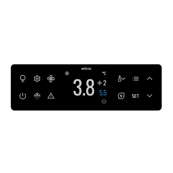
4.2
Display
MIN... MAX.
r1... r2
0 = PTC
1 = NTC
2 = Pt 1000
0 = °C
1 = °F
0 = electric
1 = hot gas
2 = compressor stopped
4.3
Switching the device on/off
1.
If the device is switched on, the display will show the P5 value (default "cabinet or product
temperature"); if the LED alarm is on, see the section ALARMS.
LED
ON
compressor on
heating active
evaporator fans on
defrost or pre-drip ac-
tive
clock active
%
active humidity level
displayed
°C
temperature displayed
in Celsius
°F
temperature displayed
in Fahrenheit
energy saving active
overcooling or over-
heating active
alarm active
HACCP saved
not displayed
cabinet light on
connection
EVconnect
EPoCA remote moni-
toring system
-
AUX1
auxiliary load 1 on
AUX2
auxiliary load 2 on
If Loc = 1 (default) and 30 s have elapsed without the keys being pressed, the display will show
the "LOCK" label and the keypad will lock automatically.
4.4
Unlocking the keypad
Touch a key for 1 s: the display will show the label "UNLOCK".
If POF = 1 (default), touch the ON/STAND-BY key for 4 s
OFF
FLASHING
compressor off
compressor protection active
heating not active
demisting on or door heaters on
evaporator fans off
evaporator fans off active
defrost or pre-drip not
- defrost delay active
active
- dripping active
clock not active
-
-
-
-
-
-
-
energy saving not ac-
-
tive
overcooling or over-
-
heating not active
alarm not active
compressor maintenance request
HACCP
alarm
no HACCP alarm saved
new HACCP alarm saved
or no saved HACCP
alarm not displayed
cabinet light off
cabinet light on from digital input
with
no connection
-
app
or
thawing not active
thawing active
auxiliary load 1 off
-
auxiliary load 2 off
-
4.5
Setting the setpoint (if r3 = 0, default)
Check that the keypad is not locked.
1.
Touch the SET key
Touch the UP or DOWN key within 15 s to set the value within the
2
limits r1 and r2 (default "-40... 50")
3.
Touch the SET key (or take no action for 15 s)
4.6
Setting the 0-10 V evaporator fan speed for normal operation (percentage 0-10
V output; available if Ao1... Ao3 = 3 and F30 = 0)
Check that the keypad is not locked.
1.
Touch the FAN key
Touch the UP or DOWN key within 15 s to set the value within the
2.
limits F31 and F32 (default "50... 100")
3.
Touch the SET key (or take no action for 15 s)
4.7
Activating/deactivating manual defrost (if r5 = 0, default)
Check that the keypad is not locked and that overcooling is not active.
1.
Touch the DEFROST key for 2 s
If P3 = 1 (default), defrost is activated provided that the evaporator temperature is lower than
the d2 or d2b threshold.
4.8
Activating/deactivating manual energy saving
Check that the keypad is not locked.
1.
Touch the ENERGY SAVING key
FUNCTION
CONDITION
energy saving
r5 = 0
If u1c... u8c = 16, the evaporator fans will operate at this speed during the energy-saving func-
tion.
If u1c... u8c = 18, the condenser fans will operate at this speed during the energy-saving func-
tion.
4.9
Activating/deactivating overcooling and overheating
Check that the keypad is not locked.
1.
Touch the OVERCOOLING/OVERHEATING key
FUNCTION
CONDITION
overcooling
r5 = 0 and defrosting not ac-
tivated
overheating
r5 = 1
4.10
Manually switching the cabinet light on/off (if u1c... u8c = 5)
1.
Touch the CABINET LIGHT key
4.11 Silencing the buzzer (if u9 = 1, default)
Touch a key.
If u1c... u8c = 11 and u4 = 1, the alarm output is deactivated.
CONSEQUENCE
the setpoint becomes "setpoint +
r4", for the HE2 time at the most
CONSEQUENCE
the setpoint becomes "setpoint -
r6", for the r7 time
the setpoint becomes "setpoint +
r6", for the r7 time
Advertisement

Subscribe to Our Youtube Channel
Related Manuals for Evco EVY Cold MEDIUM


Summary of Contents for Evco EVY Cold MEDIUM
- Page 1 EVCO S.p.A. | EVY Cold MEDIUM | Instruction sheet ver. 1.0 | Code 104YCM12E103 | Page1 of 6 | PT 18/24 EVY Cold MEDIUM Controllers for refrigerated cabinets and display units ELECTRICAL CONNECTION ENGLISH controllers for normal or low temperature units N.B.
- Page 2 EVCO S.p.A. | EVY Cold MEDIUM | Instruction sheet ver. 1.0 | Code 104YCM12E103 | Page2 of 6 | PT 18/24 ADDITIONAL FUNCTIONS Deleting compressor operation days Touch the UP or DOWN key within 15 s to select the option “Pa- Setting the date and time (available when the EVlinking RS-485 EVIF23TSX con- Check that the keypad is not locked.
- Page 3 EVCO S.p.A. | EVY Cold MEDIUM | Instruction sheet ver. 1.0 | Code 104YCM12E103 | Page3 of 6 | PT 18/24 7 = Embraco VES if values are negative, com- setpoint threshold to activate “b” r1... r2 8 = Embraco FMX...
- Page 4 EVCO S.p.A. | EVY Cold MEDIUM | Instruction sheet ver. 1.0 | Code 104YCM12E103 | Page4 of 6 | PT 18/24 maximum time evaporator fans 0... 15 min door open consecutive time for 0... 240 min PAR. DEF. MODBUS MIN... MAX.
- Page 5 EVCO S.p.A. | EVY Cold MEDIUM | Instruction sheet ver. 1.0 | Code 104YCM12E103 | Page5 of 6 | PT 18/24 NTC probes: Type of sensor: ß3435 (10 k @ 25 °C, 77 °F) Measurement field: from -40 to 105 °C (from -40 to 221 °F) Resolution: 0.1 °C (1 °F)
Need help?
Do you have a question about the EVY Cold MEDIUM and is the answer not in the manual?
Questions and answers