Table of Contents
Advertisement
Quick Links
NAU85L40 Demo Board
The PCB name: NAU85L40 DEMO board V1.0
Ordering P/N:
NL-NAU85L40
NL-NAU85L40S (Single-end microphone pattern)
The information described in this document is the exclusive intellectual property of
Nuvoton Technology Corporation and shall not be reproduced without permission from Nuvoton.
Nuvoton is providing this document only for reference purposes of microcontroller based system design.
Nuvoton assumes no responsibility for errors or omissions.
All data and specifications are subject to change without notice.
For additional information or questions, please contact: Nuvoton Technology Corporation.
JUN. 03, 2021
NAU85L40 Demo Board User Manual
User Manual
(Differential microphone pattern)
www.nuvoton.com
Page 1 of 16
Rev1.2
Advertisement
Table of Contents

Related Manuals for Nuvoton NAU85L40


Summary of Contents for Nuvoton NAU85L40
- Page 1 The information described in this document is the exclusive intellectual property of Nuvoton Technology Corporation and shall not be reproduced without permission from Nuvoton. Nuvoton is providing this document only for reference purposes of microcontroller based system design. Nuvoton assumes no responsibility for errors or omissions.
-
Page 2: Table Of Contents
NAU85L40 Demo Board User Manual TABLE OF CONTENTS OVERVIEW ................5 INTRODUCTION ................6 Top View ..................7 Input / Output (Differential microphone pattern) ......... 8 Input / Output (Single-end microphone pattern) ......... 9 Jumpers ..................10 Schematic ..................13 Bare Board ................... - Page 3 NAU85L40 Demo Board User Manual List of Figure Figure 2-1 NAU85L40 Demo Board (Differential microphone pattern) ..........6 Figure 2-2 NAU85L40 Demo Board (Single-end microphone pattern) ..........6 Figure 2.1-1 Top View ........................7 Figure 2.2-1 Input / Output(Differential microphone pattern) ............8 Figure 2.3-1 Input / Output(Single-end microphone pattern) ............
- Page 4 NAU85L40 Demo Board User Manual List of Tables Table 2.1-1 Main Components ......................7 Table 2.2-1 Input / Output (Differential microphone pattern) ............8 Table 2.3-1 Input / Output (Single-end microphone pattern) ............9 Table 2.4-1 Jumpers ........................12 JUN. 03, 2021 Page 4 of 16 Rev1.2...
-
Page 5: Overview
NAU85L40 Demo Board User Manual OVERVIEW The NAU85L40 is a low power, high quality, 4-channel ADC for microphone array application. The NAU85L40 integrates programmable gain preamplifiers for quad differential microphones, significantly reducing external component requirements. A fractional FLL is available to accurately generate any audio sample rate using any commonly available system clock source from 8KHz through 33MHz. -
Page 6: Introduction
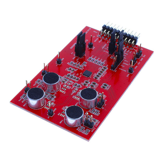
NAU85L40 Demo Board User Manual INTRODUCTION The NAU85L40 Demo Board is designed to allow a thorough evaluation of the multi analog input device. Figure 2-1 NAU85L40 Demo Board (Differential microphone pattern) Figure 2-2 NAU85L40 Demo Board (Single-end microphone pattern) JUN. 03, 2021 Page 6 of 16 Rev1.2... -
Page 7: Top View
NAU85L40 Demo Board User Manual Top View Figure 2.1-1 Top View Name Description NAU85L40 Audio ADC Table 2.1-1 Main Components JUN. 03, 2021 Page 7 of 16 Rev1.2... -
Page 8: Input / Output (Differential Microphone Pattern)
NAU85L40 Demo Board User Manual Input / Output (Differential microphone pattern) Figure 2.2-1 Input / Output(Differential microphone pattern) Name Description Pin 1 MCLK, Master Clock Pin 11 I2C Interface Pin 3 BCLK, Bit Clock Pin 13 I2S Interface Pin 7... -
Page 9: Input / Output (Single-End Microphone Pattern)
NAU85L40 Demo Board User Manual Input / Output (Single-end microphone pattern) Figure 2.3-1 Input / Output(Single-end microphone pattern) Name Description Pin 1 MCLK, Master Clock Pin 11 I2C Interface Pin 3 BCLK, Bit Clock Pin 13 I2S Interface Pin 7... -
Page 10: Jumpers
NAU85L40 Demo Board User Manual Jumpers Single-end microphone’s jumper with the same position as the Differential microphone pattern Figure 2.4-1 Jumpers Pin definition Description VDDB voltage selection 2-3(default) VDDB uses voltage of VDDB uses voltage of 1.8V 3.3V Must be consistent with the I2C voltage of the master JUN. - Page 11 NAU85L40 Demo Board User Manual Select which group of signals to use for 1-2 (default) ADCOUT of P2 Use Digital Audio ADC Data Use Digital Audio ADC Data Output for ADC 1 and 2 Output for ADC 3 and 4 or TDM output at ADCOUT of P2.
-
Page 12: Table 2.4-1 Jumpers
NAU85L40 Demo Board User Manual An external signal can be provided to MIC 3 (P12) and MIC 4(P13) (Differential microphone pattern) Table 2.4-1 Jumpers JUN. 03, 2021 Page 12 of 16 Rev1.2... -
Page 13: Schematic
NAU85L40 Demo Board User Manual Schematic Figure 2.5-1 Schematic JUN. 03, 2021 Page 13 of 16 Rev1.2... -
Page 14: Bare Board
NAU85L40 Demo Board User Manual Bare Board Figure 2.6-1 Top View of Bare Board Figure 2.6-2 Top View of Bare Board JUN. 03, 2021 Page 14 of 16 Rev1.2... -
Page 15: Connected To Audio Control Board
If there is Nuvoton's Audio Control Board, NAU85L40 Demo Board can be used with Audio Control Board (USB_I2C_I2S_Control_Board_V1.1). When the Audio Control Board is connected to the NAU85L40 Demo Board, the PC or USB host can use the GUI to control the NAU85L40 Demo Board and know the status of the NAU85L40 Demo Board... -
Page 16: Revision History
Update the contents of the user manual Important Notice Nuvoton Products are neither intended nor warranted for usage in systems or equipment, any malfunction or failure of which may cause loss of human life, bodily injury or severe property damage. Such applications are deemed, “Insecure Usage”.
Need help?
Do you have a question about the NAU85L40 and is the answer not in the manual?
Questions and answers