
Related Manuals for PicoQuant SPAD


Summary of Contents for PicoQuant SPAD
- Page 1 Dual Channel SPAD Detection Unit External Detection Unit for Laser Scanning Microscopes User's Hardware Manual and Technical Data Version 2.1...
-
Page 2: Table Of Contents
Safety Instructions LASER Warning! Laser light of class 3B lasers may be delivered via the multimode fiber into the Dual Channel SPAD Detection Unit. Therefore, the multimode fiber must not be removed from the detection unit. Do not remove any items inside the unit. The installation room of the LSM Upgrade kit to be labeled as laser area. -
Page 3: Introduction
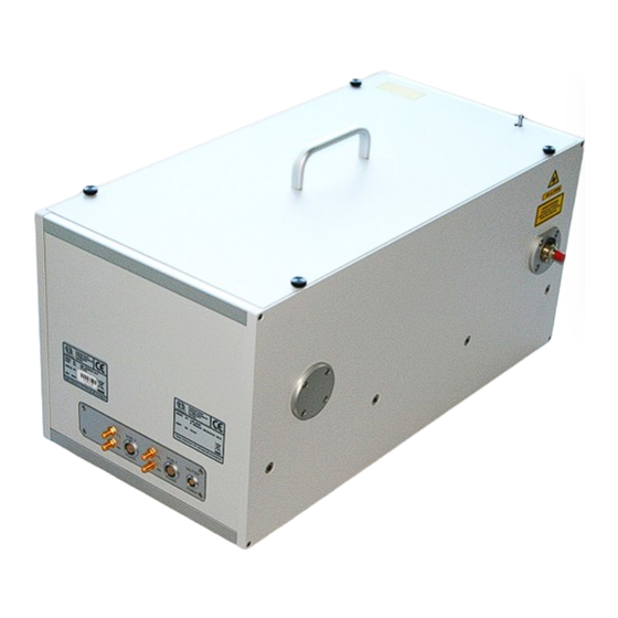
Dual Channel SPAD Detection Unit 1. Introduction This manual describes the basic components of the dual channel SPAD detection unit, as well as operation, maintenance and adjustment of the detectors . The Dual Channel Detection Unit is an external detection unit for standard confocal laser scanning microscopes (LSMs). -
Page 4: Physical Properties And Installation Requirements
Temperature variation the microscope optics cannot be excluded 3. Detector Types -SPAD Single Photon Avalanche Diode from PicoQuant • Suitable for the wavelength range from 400 nm to 1100 nm • Provides high detection efficiency (typical 45% at 470 nm and 75% at 670 nm) •... - Page 5 PicoQuant GmbH Dual Channel SPAD Detection Unit PDM Series Single Photon Avalanche Diode (MPD SPAD) • Highest sensitivity of 45 % at 530 nm • The active area in a module mounted into the two channel detection unit has 100 µm diameter.
-
Page 6: Set Up Of The Dual Channel Detection Unit
MBF3 type) fit. Replacement is easy, just open the cover and loose the screw indicated by a yellow arrow in Fig. 4.2 to slide a beam splitter cube out. After replacement, detector SPAD 2 may have to be adjusted again (See adjustment section of this manual). - Page 7 DSN 102. The complete cable scheme of your setup is part of the Appendix to your system. • The DSN can control and monitor two SPAD detectors at the same time, displaying the count ➔ rate of one selected module.
-
Page 8: Operation
The detector signals are guided to a router module (e.g. PHR 800) or to a HydraHarp TCSPC unit. • The router unit permits up to four SPAD detectors to operate quasi in parallel on the PicoHarp 300 unit. Its role is to feed the detectors’ signals into the single start input of the TCSPC device, simultaneously generating routing information (i.e. -
Page 9: Switching Off Your System
1. To check the general performance, acquire images with the normal LSM detectors and afterwards with the PicoQuant detectors. Thus a drop in performance can be easily recognized. In the following description we assume that LSM images using the standard LSM can be obtained without problems, using reasonable settings 2. -
Page 10: Detector Unit Adjustment
1. Place an empty cover slide on the microscope stage 2. Place a OD3 light attenuator at the filter holder in front of the misaligned SPAD detector. The filter is placed into the filter holder 1 or 2 for the respective detectors as shown in Fig. 4.1. - Page 11 In the case of the -SPAD adjustment, this is a relative flat, high intensity plateau with steep edges, where the intensity drops to the background count rate (Fig. 5.4), whereas the plateau is less pronounced for a MPD detector.
- Page 12 PicoQuant GmbH Dual Channel SPAD Detection Unit Fig. 5.3: Adjustment Screws for the focussing lens in front of the SPAD detector. Use the allen key size 2 mm (part of the toolbox) for detector lens adjustment. 10. The adjustment for a MPD SPAD is finished, when the lens is directed to the center of the plateau, indicating maximum count rate Fig.
-
Page 13: Fundamental Alignment Of The Dual Channel Spad Detection Unit
Switch all SPAD detectors off before performing the alignment steps! LASER Warning! Laser light of class 3B lasers may be delivered via the multimode fiber into the Dual Channel SPAD Detection Unit. Therefore, the multimode fiber must not be removed from the detection unit. As during the alignment, items within the Dual Channel Detection Unit will have to be removed, follow the laser safety rules for treating open laser beams. - Page 14 2. Make sure that in position 1 of the variable beam splitter unit a 100 % mirror is placed (compare Fig. 4.2). Fig. 5.7: Dual Channel SPAD detection unit with relevant parts for alignment 5. Place the adjustment plate (Fig. 5.6) before the detector as shown in Fig. 5.8. In case of correct adjustment, the beam is placed at the center of the adjustment plate, when shutter 2 is opened by pressing the “Hand Control Shutter 2”...
- Page 15 PicoQuant GmbH Dual Channel SPAD Detection Unit Fig. 5.8: SPAD with removed tubing and attached beam alignment tool Fig. 5.9: Fiber Outcoupling Unit at the dual detector unit. the adjustment screws are marked in red, the counter screws are marked in yellow.
-
Page 16: Recommended Literature
Benda A., Hof. M., Wahl M., Patting M., Erdmann R., Kapusta P.: TCSPC upgrade of a confocal FCS microscope. Review of Scientific Instruments, Vol.76, 033106 (2005) The following application and technical notes are available from PicoQuant upon request: Koberling F., Schuler B.: FRET analysis of freely diffusing molecules using the MicroTime 200 Krämer B., Koberling F.: Lifetime based hydrophobicity analysis of hepatocytes using the MicroTime 200... -
Page 17: Useful Www Resources
Dual Channel SPAD Detection Unit Numerous measurement examples are published on the PicoQuant website. Please visit the LSM Upgrade Kit section of http://www.picoquant.com/_systems.htm . This manual frequently refers to information in additional PicoQuant manuals, which also belong to the LSM Upgrade Kit documentation: •... -
Page 18: Abbreviations
PicoQuant GmbH Dual Channel SPAD Detection Unit 8. Abbreviations British Naval Connector or Bayonet Nut Connector or Bayonet Neill Concelman Charge-Coupled Device Constant Fraction Discriminator Counts per Second Continuous wave (not pulsed) Fluorescence Correlation Spectroscopy Fiber Coupling Unit FIFO First In, First Out (buffer type) -
Page 19: Support
Your feedback will help us to improve the product and documentation. In any case, we would like to offer you our complete support. Please do not hesitate to contact PicoQuant if you would like to have assistance with your system. - Page 20 WEEE-Reg.-Nr. DE 96457402 All trademarks mentioned in this manual are the property of their respective owners. PicoQuant claims no rights to any such trademarks used here. Products and corporate names appearing in this manual may or may not be registered trademarks or copyrights of their respective owners. They are used here only for identification or explanation and to the owner’s benefit, without intent to infringe.
Need help?
Do you have a question about the SPAD and is the answer not in the manual?
Questions and answers