
Related Manuals for PicoQuant Sepia PDL 828


Summary of Contents for PicoQuant Sepia PDL 828
- Page 1 Sepia PDL 828 Computer Controlled Multichannel Picosecond Diode Laser Driver User Manual Version 3.0.3...
- Page 3 PicoQuant GmbH Sepia PDL 828 Manual Page 3...
-
Page 4: Table Of Contents
PicoQuant GmbH Sepia PDL 828 Manual Table of Content 1. General safety information..........................8 1.1. Warning Symbols and Conventions..................... 8 1.2. Electrical Safety Instructions........................ 9 1.3. Laser Safety Instructions........................10 Required Laser Safety Measures....................10 What does the owner / operator have to observe?..............10 General Safety Instructions for Operation...................10... - Page 5 PicoQuant GmbH Sepia PDL 828 Manual VisIR modules)..........................26 3.3.5. Oscillator Module (SOM 828 and SOM 828-D)..............26 Selecting the Base Oscillator...................... 26 Setting the Main Clock Rate (Divider)..................26 Burst Lengths..........................26 Examples for Oscillator Application..................... 26 4. Hardware Description..........................27 4.1.
- Page 6 Step 3:............................47 Step 4............................47 5. Software Description........................... 48 5.1. PQLaserDrv – The Graphical User Interface (GUI) for Sepia PDL 828 et al........48 5.1.1. Select Device........................49 5.1.2. Apply / Discard........................49 5.1.3. Soft Lock and Unlock of the Sepia PDL 828................50 5.1.4.
- Page 7 PicoQuant GmbH Sepia PDL 828 Manual 6.2. PIE-STED Pulse Sequence Programming (SOM 828-D only)............63 Setting the Main Clock........................ 63 Defining the Channels......................... 63 Generating the Proper STED Burst Patterns................64 Setting the Delays and Sync Signals..................65 6.3. Getting Correct Sync Pulses from the Oscillator................65 6.4.
-
Page 8: General Safety Information
PicoQuant GmbH Sepia PDL 828 Manual 1. General safety information CAUTION! Before using this device, make sure that you have read and understood the con- tent of this user manual. Store this documentation in a safe and easily accessible place for future reference. -
Page 9: Electrical Safety Instructions
PicoQuant GmbH Sepia PDL 828 Manual 1.2. Electrical Safety Instructions WARNING! To avoid electric shock, the power cord’s protective grounding conductor must be connected to the ground. This devices modules and laser heads contain no user serviceable components. Do not remove covers! Servicing of internal components is restricted to qualified personnel. -
Page 10: Laser Safety Instructions
Read all instructions carefully BEFORE operating this device. The Sepia PDL 828 laser driver as well as laser diode heads of the LDH Series and LDH-FA Series or VisIR/VisUV laser modules are manufactured according to the International Laser Safety Standard IEC 60825-1:2014 and comply with the US law 21 CFR §1040.10 and §1040.11. -
Page 11: Laser Safety Labels
As it is impossible to anticipate every potential hazard, please be careful and apply common sense • when operating the Sepia PDL 828 laser driver and its associated diode laser heads. Observe all safety precautions relevant to class 3B / IIIB or class 3R / IIIR, respectively. -
Page 12: Long Cylindrical Heads (Ldh Series)
PicoQuant GmbH Sepia PDL 828 Manual 1.4.2. Long Cylindrical Heads (LDH Series) Fig. 2: Location of the laser safety and warning labels as well as aperture indicator on a long cylindrical laser head (here an LDH-D-TA-530). Page 12... -
Page 13: Flat Cuboid Heads (Ldh-Fa Series)
PicoQuant GmbH Sepia PDL 828 Manual 1.4.3. Flat Cuboid Heads (LDH-FA Series) Fig. 3: Location of the laser safety and warning labels as well as aperture indicator on a flat cuboid laser head (here an LDH-P- FA-530B). Page 13... -
Page 14: Tall Cubioid Heads (Ldh-Fa Series)
PicoQuant GmbH Sepia PDL 828 Manual 1.4.4. Tall Cubioid Heads (LDH-FA Series) Fig. 4: Location of the laser safety and warning labels as well as aperture indicator on a tall cuboid laser head (here an LDH-P-FA-560). Page 14... -
Page 15: Remote Interlock Connector
Fig. 5: Location of the remote interlock connectors on the front panel of the Sepia PDL 828 (highlighted by the red box). The green remote interlock connector (LEMO plug) is located on the front panel as shown in Fig. 5. -
Page 16: Third-Party Lasers
Only compatible laser heads (LDH or LDH-FA Series), pulsed LEDs (PLS Series) or stand alone laser mod- ules (e.g., VisIR or VisUV) manufactured by PicoQuant can be operated with the Sepia PDL 828 laser driver. Do NOT connect any non-PicoQuant supplied laser heads to the Sepia PDL 828. -
Page 17: Introduction
2.3. Oscillator Module The Sepia PDL 828 system offers the user unparallelled flexibility in driving up to 8 laser heads in a user de- fined sequence. The concept for a coordinated firing sequence is to synthesize triggering signals for each laser driving module in one central oscillator module. -
Page 18: Installation And Quick Start
3.1. Hardware Installation The Sepia PDL 828 is a modular device. The mainframe of the device (PDL 828 mainframe) consists of the external housing (incl. power supply, main power switch, cooling) and of the controller module (SCM 828) with laser key switch, USB port and remote interlock connector. -
Page 19: Slm 828 Laser Driver Module
These optional modules allow connecting and transparently integrating a laser module from PicoQuant’s VisIR / VisUV family to the Sepia PDL 828. The SEM 828 module also needs to be installed in one of the slots located to the right of the oscillator module inside the PDL 828 mainframe. - Page 20 PicoQuant GmbH Sepia PDL 828 Manual To install the software: 1. Insert the installation medium into the host computer 2. Launch the program: PQLaserDrv_Setup.exe 3. Follow the instructions on the screen: Fig. 7: PQ Laser Driver GUI Setup Wizard - Welcome window Fig.
- Page 21 Important Remarks: The PicoQuant Laser Driver Software can control not only the Sepia PDL 828 but also the VisIR / VisUV laser modules and Prima lasers from PicoQuant. In case you need to control multiple lasers, then it is necessary to install all relevant components (see Fig.
- Page 22 PicoQuant GmbH Sepia PDL 828 Manual Fig. 14: PQ Laser Driver GUI Setup Wizard - Driver installation Fig. 15: PQ Laser Driver GUI Setup Wizard - Driver installation Click Next to start the installation of the drivers as shown in Fig. 14 and Fig. 15.
-
Page 23: Quick Start Guide
Fig. 18: PQ Laser Driver GUI Setup Wizard - Finish Once the software is installed, the Sepia PDL 828 can be turned on (see chapter 3.3). When the laser is turned on for the first time, Windows will detect a new device and install the necessary device drivers. -
Page 24: System Indicators And Controls
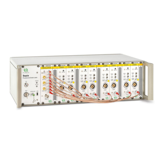
Fig. 19: Sepia PDL 828 Type "L" with SOM 828 module and eight SLM 828 modules Power button and indicator. In general use, it is recommended to turn off the Sepia PDL 828 by using this button (stand by mode). A full power down (via main power switch on the back of the device) is required for some specific tasks, such as installing or changing hardware modules (see section 4.7) -
Page 25: Laser Drivers Slm 828 And Laser Heads
PicoQuant GmbH Sepia PDL 828 Manual All parameter fields normally display the currently active values. • It is possible to change one or more parameters by entering new values, but the changes will not be • effective until they are transferred to the modules using the Apply button. Values that have been changed but not yet submitted to the hardware modules are highlighted with an orange box. -
Page 26: Sepia Extension Module Sem 828
PicoQuant GmbH Sepia PDL 828 Manual NOTICE Always use only as much power as needed for your application to prolong the lifetime of the laser diode / LED. 3.3.4. Sepia Extension Module SEM 828 (optional component for remote control of e.g., VisUV / VisIR modules) -
Page 27: Hardware Description
PicoQuant GmbH Sepia PDL 828 Manual 4. Hardware Description The PDL 828 “Sepia II” is a modular device consisting of a mainframe and a variety of possible modules that can be inserted into dedicated slots. This section describes the mainframe, the most commonly used mod - ules, and possible interactions between them. -
Page 28: Slot Numbering
Fig. 22: SCM 828 - front panel Power button and indicator. Pressing this button switches the Sepia PDL 828 from stand by mode to on, and vice versa. The LED in the button light up in red when the laser driver is in standy by mode (main power switch is in the ON position). -
Page 29: Laser Locked
ACTIVE: white LED. Lights up as soon as the power supply is on • USB-C connector to interface the Sepia PDL 828 with the PC WARNING! Laser radiation can be emitted when the white LASER ACTIVE LED is on. Refer to chapter 1.3 for laser safety instructions and chapter 3 for installation information. -
Page 30: Oscillator Module - Som 828 And Som 828-D
PicoQuant GmbH Sepia PDL 828 Manual 4.3. Oscillator Module – SOM 828 and SOM 828-D 4.3.1. Front Panel The oscillator front panel (Fig. 23) includes various connectors for the trigger and auxiliary inputs and outputs as well as a synchronization output port. The front panel layout is identical for both the SOM 828 and SOM 828-D oscillator modules. -
Page 31: Oscillator Module Som 828
PicoQuant GmbH Sepia PDL 828 Manual 4.3.2.1. Oscillator Module SOM 828 The oscillator module SOM 828 is composed of several basic function blocks, as schematically depicted in Fig. 24 (A). The scheme shows the logical interconnections of the functional modules and their (GUI / API) parameters, but does not represent the actual electrical realization. - Page 32 PicoQuant GmbH Sepia PDL 828 Manual control system on the external trigger input port in order to further improve signal quality by reduc- ing jitter and noise. 2. A prescaler to derive the main frequency from the base frequency provided by the base oscillator.
- Page 33 PicoQuant GmbH Sepia PDL 828 Manual Fig. 24: Logic function block scheme for SOM 828 (A) and SOM 828-D (B) Page 33...
-
Page 34: Oscillator Configuration
PicoQuant GmbH Sepia PDL 828 Manual 4.3.3. Oscillator Configuration 4.3.3.1. Main Clock Definition The main clock is the input signal of the sequencing stage. It is the time graticule to which any output pulses of the SOM 828 and SOM 828-D refer. The main clock period represents the minimal timing distance between any two output pulses. -
Page 35: Burst Length
PicoQuant GmbH Sepia PDL 828 Manual Burst Length The number of pulses in a burst channel is defined by the burst length parameter and can be varied between 1 and 16.7 millions. Once the number of pulses set has been emitted, the sequencer switches to the next burst channel. -
Page 36: Sync Enable
PicoQuant GmbH Sepia PDL 828 Manual It is possible to control: 1. whether a specific output channel should generate pulses at the sync output at all (“Sync enable”) 2. a time shift to position the sync pulse prior to its corresponding output pulse (“Pre sync”), 3. -
Page 37: Auxiliary Input / Output
PicoQuant GmbH Sepia PDL 828 Manual In the reverse case, i.e., only a certain number of synchronization pulses are required at the beginning of a burst pattern, the Sync Mask function can be inverted. Fig. 27 illustrates how the pattern changes when the mask is inverted. - Page 38 PicoQuant GmbH Sepia PDL 828 Manual NOTICE The auxiliary output AUX OUT delivers TTL levels only to high impedance signal sinks. On 50 Ohms terminated lines, the signal level drops down to approximately 500 mV. The timing of the AUX OUT signals will not meet the same high slew rate / low jitter specifications as the NIM output signals.
-
Page 39: Sepia Laser Modules - Slm 828
The laser driver module generates all of the signals and supply voltages for the picosecond laser heads and sub-nanosecond LED heads provided by PicoQuant. Only laser heads supplied by PicoQuant can be used with the laser driver. A direct connecting of other types of laser diodes to the driver is not supported. The laser heads contain a unique circuit that matches the laser diodes to the driving electronics. -
Page 40: Operation Mode And Triggering
(PRF) supported by some laser heads. This could result in overheating of the laser head. Although PicoQuant laser heads are protected against damages caused by excess PRF, it is strongly recommended to avoid such situations. Refer to the test sheet of your laser head for its individual maximum PRF. -
Page 41: Emission Intensity
PicoQuant GmbH Sepia PDL 828 Manual 4.4.3. Emission Intensity The intensity of the laser emission is controlled via internal voltage in steps of 1‰ of its full scale value. It is important to note that this voltage does not correlate linearly to its optical output power. Also note that some high-powered laser heads may only operate at very high levels of the intensity control. -
Page 42: Sepia Extension Module - Sem 828 (Optional Component For Remote Control Of Of E.g., Visuv / Visir Modules)
WARNING! Laser Safety Note that the connected device may be of a higher laser class than the Sepia PDL 828 (e.g., a Class 4 / IV VisUV or VisIR). When such a device is connected to the SEM, then all laser safety measures applicable to its laser class also need to be observed. -
Page 43: Front Panel
PicoQuant GmbH Sepia PDL 828 Manual 4.5.1. Front Panel Fig. 31: SEM 828 front panel SEM laser connector: the VisIR / VisUV laser module has to be connected to this port with its cable. Make sure that the red markings on both cable connector and output port are matched. -
Page 44: Laser Heads / Led Heads
PicoQuant GmbH Sepia PDL 828 Manual 4.6. Laser Heads / LED Heads 4.6.1. Temperature Controlled (Model LDH–…–C Laser Heads Only) The only user adjustable part of the laser head is the set-point for the thermoelectric (TE) cooler. Since the output power at a given potentiometer setting depends slightly on the temperature of the diode element, the set-point should only be changed if absolutely necessary, e.g., if the ambient temperature is too high. - Page 45 PicoQuant GmbH Sepia PDL 828 Manual The temperature of the diode element needs to reach the set-point temperature for stable operation. At start- up the status LED may be "red“. The laser head will switch off if the LED is “red“ and the diode element is warmer than approx.
-
Page 46: Pdl 828 Hardware Upgrade
Performing the hardware upgrade is easy and straightforward and is outlined in this section. CAUTION! Fully power down the Sepia PDL 828 and disconnect the power cable from the device prior to performing the procedure outlined below. Ensure that you follow proper ESD (electrostatic discharge) protection rules to avoid damaging the device. -
Page 47: Step 3
PicoQuant GmbH Sepia PDL 828 Manual Fig. 35: Location of red guide rails Step 3: Take the new module (e. g., SLM 828 as shown in Fig. 36) and carefully insert it into the empty slot using the red guide rails. -
Page 48: Software Description
SOM 828, a SEM 828 module, which is connected to a VisIR-1950-F module and a laser driver modules SLM 828. Fig. 38: Sepia PDL 828 GUI - Overview with all control groups with indication of the individual sections Page 48... -
Page 49: Select Device
Sepia PDL 828 (or any other USB laser device from PicoQuant) are connected to the same host computer. It can also be used to restore the USB connection to the device should it be lost during operation for any reason. -
Page 50: Soft Lock And Unlock Of The Sepia Pdl 828
Soft Lock and Unlock of the Sepia PDL 828 The Sepia PDL 828 can be locked (no laser light emission) and unlocked (laser light is emitted) not only with the hardware key switch on the front panel, but also via the GUI by clicking on the button labeled Laser Soft Lock / Laser Soft Unlock , which is located in the controller frame on the left side of the software window. -
Page 51: Oscillator Module Som 828
PicoQuant GmbH Sepia PDL 828 Manual 5.1.4. Oscillator Module SOM 828 The control panel for the SOM 828 is shown in Fig. 44 below: Fig. 44: Control element for the SOM 828 Set Main Clock and Trigger: The frequency of the main clock is derived from the chosen base oscillator (80 MHz, 64 MHz, or 50 MHz) or external Trigger source (rising edge or falling edge) and from the dividing factor Divider. -
Page 52: Define Sync Signal By Presync, Sync Mask And Invert
PicoQuant GmbH Sepia PDL 828 Manual The text field labeled Sequencer period at the control panel bottom summarizes the content of the whole sequencer period (total amount of pulses, sequence period length, and sequence repetition rate). Note that this timing information cannot be displayed when the SOM 828 is triggered externally. -
Page 53: Set Auxiliary Input / Output
PicoQuant GmbH Sepia PDL 828 Manual Fig. 48: Visualization of the output bursts as set in Fig. 44. Set Auxiliary Input / Output: The auxiliary input can be used in order to disable or enable the sequencer of the oscillator module. -
Page 54: Oscillator Module Som 828-D
PicoQuant GmbH Sepia PDL 828 Manual 5.1.5. Oscillator Module SOM 828-D Schaubild 1: Control elements for the SOMD 828 The GUI of the SOM 828-D shares most of the control elements with the SOM 828, as shown in Fig. 53. -
Page 55: Sequencer Configuration Panel
PicoQuant GmbH Sepia PDL 828 Manual synchronization with the PLL control element. Furthermore, the signal quality of a generator can be frequency dependent. It might happen that a frequency generator can supply suitable signals at some frequencies, while other frequencies will fail to synchronize with the PLL. - Page 56 PicoQuant GmbH Sepia PDL 828 Manual that the delays are not represented by a shift in the graphical display but by showing the pulse train of the corresponding channel as a green line. The delay value is also indicated in the channel output comments in the left part of the window.
-
Page 57: Sepia Laser Module Slm 828
The SEM 828 module allows modifying settings (e.g., intensity, repetition rate, trigger source) of the con- nected device directly from the Sepia PDL 828 software. The connected device then operates according to these settings. -
Page 58: Presets
To ensure laser safety, the Sepia PDL 828 will control the interlock state of a connected stand alone laser module (such as a VisUV). This has the following consequences: if the interlock is triggered by the Sepia PDL 828, then laser emission is shut down for all laser heads •... -
Page 59: About
PicoQuant GmbH Sepia PDL 828 Manual 5.1.9. “About...” button Extended information about the device, including hardware version, serial number, operating hours, software and firmware version etc. can be brought up by clicking on the button labeled About... For every support request its is recommend to save the entire information by clicking on the button labeled Copy Support Infos (see Fig. -
Page 60: Application Hints
PicoQuant GmbH Sepia PDL 828 Manual 6. Application Hints This section explains some practical example of configuration for the oscillator module (both SOM 828 and SOM 828-D). 6.1. Step-by-Step Configuration of the Oscillator Module The following configuration example is intended to demonstrate all usable options of the Sepia II oscillator module SOM 828. -
Page 61: Enable Burst Output
PicoQuant GmbH Sepia PDL 828 Manual Enable Burst Output Next, configure the output channels: The enable check boxes for channel 1 and channel 3 need to be ticked at least as these will be connected to the laser driver modules. -
Page 62: Add Identical Channels
PicoQuant GmbH Sepia PDL 828 Manual Fig. 60: Sync Mask = 2: leading two sync pulses are suppressed Fig. 59: Sync Mask = 0: pulses throughout phase four Fig. 62: Pre Sync = 2: Sync pulses are left-shifted against burst Fig. -
Page 63: Pie-Sted Pulse Sequence Programming (Som 828-D Only)
PicoQuant GmbH Sepia PDL 828 Manual 6.2. PIE-STED Pulse Sequence Programming (SOM 828-D only) This section contains a step-by-step guide to configuring the SOM 828-D oscillator module with a pulse sequence typically used in microscopy for Pulsed Interleaved Excitation (PIE) with confocal and STED reso- lution. -
Page 64: Generating The Proper Sted Burst Patterns
PicoQuant GmbH Sepia PDL 828 Manual main main clock clock Fig. 64: PIE-STED pulse pattern after definition of burst channels and lengths (left part) and combination (right part). Generating the Proper STED Burst Patterns As currently set, the STED laser burst channel is producing two pulses synchronized with each of the burst channels 1 and 2 (see Fig. -
Page 65: Setting The Delays And Sync Signals
PicoQuant GmbH Sepia PDL 828 Manual Setting the Delays and Sync Signals As mentioned above, a short delay of a few hundred picoseconds is needed between the excitation and cor- responding STED pulse. Since the STED burst channel already uses the combiner, no electronic delay can be introduced in this burst channel. -
Page 66: Choosing The Correct Laser Intensity
PicoQuant GmbH Sepia PDL 828 Manual 6.4. Choosing the Correct Laser Intensity To ensure safer working conditions and to prolong the lifetime of the laser element, select a lower power set- ting (approx. 35% of full power). Full laser power should not be used unless it is absolutely needed. This ap- plies especially to laser diodes in the ultraviolet to blue region, which still have a shorter lifetime than red or infrared laser diodes. -
Page 67: Technical Data / Specifications
PicoQuant GmbH Sepia PDL 828 Manual 7. Technical Data / Specifications Mainframe Large, L........1 slot for oscillator module, 8 slots for laser driver modules Small, S:........1 slot for oscillator module, 2 slots for laser driver modules Power supply......115/230 VAC, 50/60 Hz, max. 350 Watts Grounding......... -
Page 68: Laser Driver Module
PicoQuant GmbH Sepia PDL 828 Manual Laser Driver Module Inputs ........1 trigger (NIM), 2 gating (TTL) Outputs........1 synchronization (NIM) Operation mode......pulsed or continuous-wave Master oscillator frequency..80 MHz Repetition frequency....80, 40, 20, 10, 5, or 2.5 MHz (user-selectable) Gating Inputs Slow gate........ -
Page 69: Support
PicoQuant GmbH Sepia PDL 828 Manual 8. Support 8.1. Returning Products for Repair Should you encounter problems that require sending the device in for inspection / repair, please contact us first at: https://support.picoquant.com support@picoquant.com and request an RMA number before ship- ping the device. -
Page 70: Legal Terms
Sepia PDL 828 Manual 9. Legal Terms 9.1. Copyright Copyright of this manual and on-line documentation belongs to PicoQuant GmbH. No parts of it may be reproduced, translated, or transferred to third parties without written permission of PicoQuant 9.2. Trademarks Other products and corporate names appearing in this manual may or may not be registered trademarks or subject to copyrights of their respective owners. -
Page 71: 10. Further Reading
10.1. PicoQuant Bibliography PicoQuant maintains a database of publications mentioning PicoQuant devices. It can be found at our web - site https://www.picoquant.com/scientific/references. It is a valuable source if you would like to know which laboratories are using PicoQuant products or how broad the field of various applications is. -
Page 72: 11. Appendix
For this reason we recommend to unplug the Sepia PDL 828 from the main power supply and to wait for ca. 3 minutes to ensure a complete re- set of the controller. -
Page 73: Naming Scheme Of The Ldh Series Laser Heads
Overview of Laser Warning Labels by Model Type The table in this section provides an overview of laser warning labels by model type. Note that this list ist not exhaustive and encompasses Sepia PDL 828 compatible laser heads available at the time this manual was released. - Page 74 PicoQuant GmbH Sepia PDL 828 Manual Model type Warning label on the laser head LDH-D-TA-532 Part No.: 91 LDH-D-TA-595 Part No.: 91 LDH-D-TA-5 Part No.: 91 LDH-FA Series Page 74...
- Page 75 PicoQuant GmbH Sepia PDL 828 Manual Model type Warning label on the laser head LDH-P-FA-266 Part No.: 910266 LDH-P-FA-355 Part No.: 910355 LDH-P-FA-515L Part No.: 910517 LDH-P-FA-530B Part No.: 910531 LDH-D-FA-530L Part No.: 912534 Page 75...
- Page 76 PicoQuant GmbH Sepia PDL 828 Manual Model type Warning label on the laser head LDH-P-FA-530L Part No.: 910533 LDH-P-FA-530XL Part No.: 910534 LDH-P-FA-560 Part No.: 910560 LDH-P-FA-595B Part No.: 910596 LDH-D-FA-765L Part No.: 912766 Page 76...
- Page 77 PicoQuant GmbH Sepia PDL 828 Manual Model type Warning label on the laser head LDH-P-FA-765XL Part No.: 910765 LDH-P-FA-775B Part No.: 910765 LDH-P-FA-1060 Part No.: 911065 LDH-P-FA-1060XL Part No.: 911066 LDH-P-FA-1530XL Part No.: 911532 Page 77...
-
Page 78: Table Of Error Codes
PicoQuant GmbH Sepia PDL 828 Manual 11.4. Table of Error Codes The following Table summarizes all error codes that can be output by the Sepia PDL 828 laser driver. Please include any generated errors codes when contacting support. Symbol Error Text... - Page 79 PicoQuant GmbH Sepia PDL 828 Manual Symbol Error Text SEPIA2_ERR_USB_INIT_FAILED -3200 USB: init failed SEPIA2_ERR_USB_INVALID_ARGUMENT -3201 USB: invalid argument SEPIA2_ERR_USB_DEVICE_STILL_OPEN -3202 USB: device still open SEPIA2_ERR_USB_NO_MEMORY -3203 USB: no memory SEPIA2_ERR_USB_OPEN_FAILED -3204 USB: open failed SEPIA2_ERR_USB_GET_DESCRIPTOR_FAILED -3205 USB: get descriptor failed...
- Page 80 PicoQuant GmbH Sepia PDL 828 Manual Symbol Error Text SEPIA2_ERR_SOM_INT_OSCILLATOR_S_FREQ_LIST_NOT_FOUND -5001 SOM: int. oscillator's freq.-list not found SEPIA2_ERR_SOM_TRIGGER_MODE_LIST_NOT_FOUND -5002 SOM: trigger mode list not found SEPIA2_ERR_SOM_TRIGGER_LEVEL_NOT_FOUND -5003 SOM: trigger level not found SEPIA2_ERR_SOM_PREDIVIDER_PRETRIGGER_OR_TRIGGERMASK_NOT_FOU -5004 SOM: predivider, pretrigger, triggermask not found...
- Page 81 PicoQuant GmbH Sepia PDL 828 Manual Symbol Error Text SEPIA2_ERR_SOMD_HW_CRC_ERROR_ON_WRITING_FIRMWARE -5113 SOMD HW: CRC error on writing firmware SEPIA2_ERR_SOMD_HW_CALIBRATION_DATA_NOT_FOUND -5114 SOMD HW: calibration data not found SEPIA2_ERR_SOMD_HW_WRONG_EXTERNAL_FREQUENCY -5115 SOMD HW: wrong external frequency SEPIA2_ERR_SOMD_HW_EXTERNAL_FREQUENCY_NOT_STABLE -5116 SOMD HW: external frequency not stable...
- Page 82 PicoQuant GmbH Sepia PDL 828 Manual Symbol Error Text SEPIA2_ERR_SWS_VALUE_OUT_OF_BOUNDS -7106 Solea SWS: value out of bounds SEPIA2_ERR_SWS_MODULE_BUSY -7107 Solea SWS: module busy SEPIA2_ERR_SWS_FW_WRONG_COMPONENT_ANSWERING -7109 Solea SWS FW: wrong component answering SEPIA2_ERR_SWS_FW_UNKNOWN_HW_MODULETYPE -7110 Solea SWS FW: unknown HW moduletype SEPIA2_ERR_SWS_FW_OUT_OF_MEMORY...
- Page 83 PicoQuant GmbH Sepia PDL 828 Manual Symbol Error Text Solea SWS HW: module 1, all motors: flash write SEPIA2_ERR_SWS_HW_MODULE_1_ALL_MOTORS_FLASH_WRITE_ERROR -7305 error SEPIA2_ERR_SWS_HW_MODULE_1_ALL_MOTORS_OUT_OF_BOUNDS -7306 Solea SWS HW: module 1, all motors: out of bounds SEPIA2_ERR_SWS_HW_MODULE_1_I2C_FAILURE -7307 Solea SWS HW: module 1: I2C failure...
- Page 84 PicoQuant GmbH Sepia PDL 828 Manual Symbol Error Text SEPIA2_ERR_SWS_HW_MODULE_2_MOTOR_3_PLAUSI_CHECK -7432 Solea SWS HW: module 2, motor 3: plausi check SEPIA2_ERR_SWS_HW_MODULE_2_MOTOR_3_DAC_SET_CURRENT -7433 Solea SWS HW: module 2, motor 3: DAC set current SEPIA2_ERR_SWS_HW_MODULE_2_MOTOR_3_TIMEOUT -7434 Solea SWS HW: module 2, motor 3: timeout...
-
Page 85: Abbreviations
PicoQuant GmbH Sepia PDL 828 Manual 11.5. Abbreviations Application Programming Interface British Naval Connector or Bayonet Nut Connector or Bayonet Neill Concelman CAMAC Corporations and Markets Advisory Committee Continuous Wave Dynamic Link Library Graphical User Interface International Electrotechnical Commission Laser Diode Head... - Page 86 PicoQuant GmbH Sepia PDL 828 Manual Page 86...
Need help?
Do you have a question about the Sepia PDL 828 and is the answer not in the manual?
Questions and answers