Sign In
Upload
Download
Table of Contents
Contents
Add to my manuals
Delete from my manuals
Share
URL of this page:
HTML Link:
Bookmark this page
Add
Manual will be automatically added to "My Manuals"
Print this page
×
Bookmark added
×
Added to my manuals
Manuals
Brands
Emec Manuals
Water Pump
F Series
Operating manual
Emec F Series Operating Manual
Solenoid driven metering pumps with diaphragm
Hide thumbs
1
2
3
4
5
6
7
8
9
10
11
12
13
14
15
16
17
18
19
20
21
22
23
24
25
26
27
28
29
30
31
32
33
34
35
36
37
38
39
40
41
42
Table Of Contents
43
44
page
of
44
Go
/
44
Contents
Table of Contents
Troubleshooting
Bookmarks
Table of Contents
General Safety Guidelines
Purpose of Use and Safety
Environmental Safety
Labels
Spare Parts
Introduction
Unpacking
General Description
Before to Install Warnings
Installation Draw
Hydraulic Installation
Electrical Installation
Models
Priming
Troubleshooting
Fuse and Main Board Replacement
Main Board
A Appendix. Maintenance
B Appendix. Construction Materials and Technical Info
C Appendix. Delivery Curves
C Appendix. Delivery Curves
C Appendix. Delivery Curves (Self Venting)
D Appendix. Dimensions
E Appendix. Chemical Compatibility Table
F Appendix. "F" and "FA" Series Pump Installation Drawings
G Appendix. "F" and "FA" Series Pump Exploded View
Advertisement
Quick Links
Download this manual
F - FA
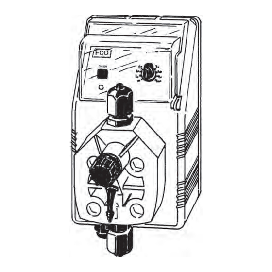
PRODUCT LABEL
EN
SOLENOID DRIVEN METERING PUMPS
WITH DIAPHRAGM
Table of
Contents
Previous
Page
Next
Page
1
2
3
4
5
Advertisement
Table of Contents
Need help?
Do you have a question about the F Series and is the answer not in the manual?
Ask a question
Questions and answers
Related Manuals for Emec F Series
Water Pump Emec FCO Operating Manual
Solenoid driven metering pumps with diaphragm (44 pages)
Water Pump Emec FTE Operating Manual
Solenoid driven metering pumps with diaphragm (44 pages)
Water Pump Emec KMS MF Operating Manual
Solenoid driven metering pumps with diaphragm (68 pages)
Water Pump Emec AMS Series Operating Manual
Solenoid driven metering pumps with diaphragm (45 pages)
Water Pump Emec RACV Operating Instructions Manual
Pneumatic dosing pump (12 pages)
Water Pump Emec TMS DC Series Operating Instructions Manual
(45 pages)
Water Pump Emec PRIUS P Operating Manual
Motor driven plunger metering pump (28 pages)
Water Pump Emec K PLUS Operating Instructions Manual
Solenoid driven metering pumps with diaphragm (222 pages)
Water Pump Emec VMS MF Series Operating Manual
Solenoid-driven diaphragm dosing pump (56 pages)
Water Pump Emec AMS CO PLUS Quick Manual
(4 pages)
Water Pump Emec KMS MF Operating Manual
Solenoid-driven diaphragm dosing pump (60 pages)
Water Pump Emec KMS Operating Manual
Solenoid driven metering pumps with diaphragm (56 pages)
This manual is also suitable for:
Fa series
Fco
Fcl
Fic
Fis
Fpv
...
Show all
Fpvm
Fte
Fpdr
Table of Contents
Print
Rename the bookmark
Delete bookmark?
Delete from my manuals?
Login
Sign In
OR
Sign in with Facebook
Sign in with Google
Upload manual
Upload from disk
Upload from URL


Need help?
Do you have a question about the F Series and is the answer not in the manual?
Questions and answers