Page 1
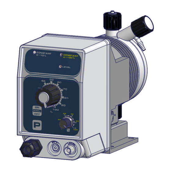
K PLUS - K CL PLUS - K CO PLUS Self-venting version: KA PLUS Viscous liquids: K PLUS LPV PRODUCT LABEL K CL PLUS Progettato da: Controllato da: Data: Peso Lordo: Peso Netto: Toll. Gen. Massimo_F Massimo_F 31/05/2013 ±0.05 Materiale:...
Page 2
This operating instructions contains safety information that if ignored can endanger life or result in serious injury. Read these instructions carefully before use and keep them for future reference. The original instruction is in English. All non-english instructions are translations of the original instruction. Information and specifications on this manual could be uncorrect or could have printing errors.
Page 3
PURPOSE OF USE METERING PUMP IS INTENDED FOR CHEMICAL DOSING. AND SAFETY Do not use in explosive area (EX). Do not use with flammable chemicals. Do not use with radioactive chemicals. Use after a proper installation. Use the pump in accordance with the data and specifications printed on the label. Do not modify or use in a manner inconsistent with the provisions of the operating manual.
Page 4
ENVIRONMENTAL Work area SAFETY Always keep the pump area clean to avoid and/or discover emissions. Recycling guidelines EWC code: 16 02 14 Always recycle according to these guidelines: 1. If the unit or parts are accepted by an authorized recycling company, then follow local recycling laws and regulations.
Page 5
DO NOT TRASH PACKAGING. USE IT TO RETURN THE PUMP. Transportation and storage temperature ..10-50°C (32-122°F) Umidity ............95% relative humidity (not condensed) Included into package K CL K CO K CL KA CO K PLUS K PLUS PLUS PLUS QUANTITY CONTENT PLUS PLUS PLUS...
Page 6
Air supply pressure range must be from 6 to 10 bar. Viscosity up to K PLUS LPV is the K version with PMMA pump head for liquids with max viscosity 8.000 cPs. 8.000 cPs: Funtioning mode is the same as K PLUS.
Page 7
Fig. 2. K PLUS - KA PLUS Modificato da Progettato da Controllato da Data Toll. Gen. Massimo_F 0.05 16/11/2010 Materiale: Edizione Foglio A3emec...
Page 8
Fig. 3. K PLUS - KA PLUS with PMMA pump head. to delivery hose Venting knob to manual to suction hose venting hose Progettato da: Controllato da: Data: Peso Lordo: Peso Netto: Toll. Gen. Massimo_F Massimo_F 08/07/2016 ±0.05 Materiale: CORPO POMPA "L" PMMA X POMPE "AMS/K/T"...
Page 9
Tab. 1. Capacity (manual and self venting models) CAPACITY peak Amps cc per Flow Mod. stroke Delivery pressure pulse/ Suction Pump K PLUS hose K PLUS LPV hose head (PVDF) cc/h 2001 0,03 0,000008 0,03 0,09 1.45 4 x 6 4 x 6 1802...
Page 10
FOOT FILTER LEVEL PROBE ✓ CABLE Materiali di PVDF PPV0 PMMA GLASS PTFE FKM B EPDM costruzione ✓ ✗ K PLUS LPV ✓ PUMP HEAD ✓ DIAPHRAGM ✓ BALLS ✓ SUCTION HOSE ✓ DELIVERY HOSE ✓ PRIMING HOSE ✓ ✗...
Page 11
INSTALLATION How to install 5 steps to install and start-up the pump: metering pump Pump location Piping connections (hoses, level probe, injection valve) Wirings Pump priming Programming and start-up The operator must be aware of safety precautions to prevent physical injury. POWER SUPPLY DISCONNECTION User health and safety...
Page 13
PIPING CONNECTIONS Foot filter / Level Level probe is assembled with a foot filter that avoid sediments priming probles. probe Install level probe on the bottom of the tank. (included only in Connect BNC level probe to the pump BNC input. some models) Warning: If there is a mixer installed into tank, install a suction lance instead of level probe / foot filter.
Page 14
Suction hose Suction piping should be as short as possible and installed in vertical position to connection avoid air bubbles suction. Completely unscrew tightening nut from pump’s head and remove assembling components: tightening nut, holding ring and pipe holder. Assembly as shown in fig. 5. Insert hose into pipe holder until it reaches the bottom.
Page 15
Insert one side of venting hose into discharge connector as shown in fig 8. Insert other side of venting hose into product’s tank. During priming procedure product exceeding will flow into tank. Fig. 8. Manual venting pump head model (K PLUS). fig. 9a. PVDF pump head connections. fig.9b. PMMA pump head connections.
Page 16
KA PLUS self Refer to fig. 9 for delivery and venting hose. venting pump Assembling procedures are the same described before. head connection Fig. 9. Self-venting models pump head: IA, LA, MA, (KA PLUS). fig. 10a. PVDF pump head connections. fig.
Page 17
WIRING THE ELECTRICAL WIRINGS SHOULD BE CARRIED OUT BY AUTHORIZED AND Preliminary checks QUALIFIED PERSONNEL ONLY IN ACCORDANCE WITH LOCAL REGULATIONS. Before to proceed, verify the following steps: Verify the data on nameplate. Make sure that the electrical data on the nameplate of the motor corresponds to the electrical supply.
Page 18
Foglio A3emec Power supply Level probe input (not on KCO PLUS model) INPUT for water meter or mA signal (only K PLUS) Level alarm output If present, connect level alarm (blue and brown wires). (option) Level alarm is free contact and not fuse protected output.
Page 19
PRIMING Warnings Feeder should be interlocked with a no-flow protection device to automatically shut-off the pumps when there is no flow! Adequate measures shall be taken to prevent cross connection of chemicals! Chemical feeding must be stopped during backwash cycles and periods of noflow as these conditions may introduce the potential for chemical overdosing.
Page 20
CONTROL PANEL K PLUS K CL PLUS K CO PLUS Keyboard function "P" KEY / PROGRAMMING MODE ENTER/EXIT ON/OFF - SCROLL PROGRAMS STROKE LENGHT ADJUSTMENT KNOB (0-100%) K PLUS - STROKE FREQUENCY ADJUSTMENT (yellow labelled scale 0-100%) or - DIVIDER MULTIPLIER FACTOR ADJUSTMENT N (grey labelled scale N: 1-10)
Page 21
LEVEL led Red level led blinks in different ways described in the table Tab. 4. Led LEVEL STATE SOLUTION Product end (if present a level Permanent red Fill the tank probe) / tank empty 3 blinks per Power supply is under the Check power supply correspond to pump second range (refer to pump label)
Page 22
PROGRAMMING THE PUMP Start/shutdown Connet power supply cable and start the pump with ON/OFF key. Led will be on the last program set (default setting: ). In OFF mode led will blink once every 2 seconds on the last program set (default setting: ). •...
Page 23
mA mode Current from an external device (BNC input) drives the pump that doses proportionally according to the minimum and maximum set (0-20 mA or 4-20 mA). To set press SCROLL until mA led turn on (red for 0-20 mA; green for 4-20 mA) and confirm with P key.
Page 24
MULT 1÷10 External pulses are multiplied by a value set by MULTIPLIER FACTOR ADJUSTMENT KNOB. mode To set press SCROLL until MULT 1÷10 led turn on, then confirm with P key..an external signal produces low pulses number. This working mode To choose if...
Page 25
TROUBLESHOOTING Tab. 7. Guide to troubleshooting PROBLEM CAUSE REMEDY • Connect to main voltage • Pump not powered ⎘ • Replace fuse Fuse replacement procedure Pump does not start • Protection fuse ⎘ • Replace main board Main board replacement •...
Page 26
Fuse replacement Make sure that the product is isolated from the power supply and cannot be powered procedure by mistake. This procedure SHOULD BE CARRIED OUT BY AUTHORIZED AND QUALIFIED PERSONNEL In order to replace fuse, you need these tools:i: •...
Page 28
MAINTENANCE Maintenance In order to ensure the requirements of potable drinking water treated and the schedule maintenance of the improvements as declared by the manufacturer, this equipment must be checked at least once a month. OPERATOR PROTECTION Use safety equipment according to the company regulations. Use this safety equipment within the work area during installation, service and when handling chemicals: •...
Page 29
f the pump performance does not satisfy your process requirements, and the process requirements have not changed, then perform these steps: 1. Disassemble the pump. 2. Inspect it. 3. Replace worn parts. This procedure SHOULD BE CARRIED OUT BY AUTHORIZED AND QUALIFIED Shutdown procedure PERSONNEL...
Page 30
Delivery curves Flow rate indicated is for H O at 20°C at the rated pressure. Dosing accuracy ± 2% at constant pressure ± 0,5 bar. Fig. 13. K PLUS delivery curves 2001: 1802: l/h 01 bar 20 l/h 2 bar 18 Pump head mod.
Page 31
0501: l/h 1 bar 5 0301: l/h 1 bar 3 Pump head mod. I Pump head mod. I 0218: l/h 18 bar 2 Pump head mod. M...
Page 32
Fig. 14. K A PLUS delivery curves 1801: l/h 1 bar 18 1503: l/h 3 bar 15 Pump head mod. LA Pump head mod. LA 085,5: l/h 5,5 bar 8 103,5: l/h 3,5 bar 10 Pump head mod. LA Pump head mod. LA 0213: 057,5,5: l/h 13 bar 2...
Page 33
Fig. 15. K AC PLUS delivery curve 1018: l/h 18 bar 10 Pump head mod. M...
Page 35
COMPATIBILITY TABLE Chemical Solenoid driven metering pumps are widely used to dose chemical fluids and it is important that the compatibility most suitable material in contact with fluid is selected for each application. This compatibility table serves table as a useful help in this respect. All the informations in this list are verified periodically and believed to be correct on the date of issuance.
Page 36
Hose resistance Hose features are very important for a reliable dosage. Every pump’s model is made to work in the table best way using selected hoses according to pump’s capacity / model. Information reported here are intended for standard use only. For extended information ask to hose’s manufacturer. Tab.
Page 37
MOD 7.5 B1 Q Ed. 1 - rev. 0 21/02/2012 PRODUCT SERVICE REPAIR FORM ENCLOSE THE PRESENT FORM TO THE DELIVERY NOTE DATE ..........SENDER Company name ............................Address ..............................Phone no..............................Contact person............................. PRODUCT TYPE (see product label) DEVICE CODE ..............................
Page 38
Included into package ........5 Fuse replacement procedure ......25 Main board replacement procedure ....25 DESCRIPTION ..........6 Main board ............ 26 K PLUS ............6 K CO PLUS ............. 6 MAINTENANCE ...........27 K CL PLUS ............6 Maintenance schedule ........27 Self venting: KA PLUS ........
Page 39
Suction hose assembling ..........13 Fig. 7. Delivery hose / pump head assembling ......13 Fig. 8. Manual venting pump head model (K PLUS)....14 Fig. 9. Self-venting models pump head: IA, LA, MA, (KA PLUS). 15 Fig. 10.
Page 40
Disposal of end-of-life equipment by users This symbol warns you not to dispose of the product with normal waste. Respect human health and the environment by giving the discarded equipment to a designated collection center for the recycling of electronic and electrical equipment. For more information visit the online site.
Page 41
“K PLUS” series metering pumps Data Sheet • Foot mounted R100523 • Microprocessor technology • Constant or proportional feeding • Manual stroke length adjustment • Manual venting (K) or self venting (KA) pump head • Enclosure ..........PP • Environment temperature ......10-45°C (55-113°F) •...
Page 42
Delivery hose 12 VDC (10-16 VDC) 3.15A Suction hose Discharge hose m 2,5 Input signal cable (only K PLUS) Operating manual Specifications subject to change without notice. Via Donatori di sangue, 1 - 02100 Rieti - Italy ISO 9001:2015 EN R1-07-15 Tel.
Page 43
“K PLUS” series metering pumps Data Sheet Dimension mm [inches] Specifications subject to change without notice. Via Donatori di sangue, 1 - 02100 Rieti - Italy ISO 9001:2015 EN R1-07-15 Tel. +39 0746 2284 1 - Fax +39 0746 2284 2 - http://www.emecpumps.com...
Page 44
KMS DC - KMSA DC PRODUCT LABEL KMS DC KMSA DC SOLENOID DRIVEN METERING PUMPS WITH DIAPHRAGM...
Page 45
This operating instructions contains safety information that if ignored can endanger life or result in serious injury. Read these instructions carefully before use and keep them for future reference. Information and specifications on this manual could be uncorrect or could have printing errors. Specifications are subject to change without notice.
Page 46
PURPOSE OF USE METERING PUMP IS INTENDED FOR CHEMICAL DOSING AND DRINKING WATER AND SAFETY TREATMENT. Do not use in explosive area (EX). Do not use with flammable chemicals. Do not use with radioactive chemicals. Use after a proper installation. Use the pump in accordance with the data and specifications printed on the label.
Page 47
ENVIRONMENTAL Work area SAFETY Always keep the pump area clean to avoid and/or discover emissions. Recycling guidelines EWC code: 16 02 14 Always recycle according to these guidelines: 1. If the unit or parts are accepted by an authorized recycling company, then follow local recycling laws and regulations.
Page 48
TRANSPORTATION A not suitable transportation or storage can cause damages. AND STORAGE Use origianal box to pack the pump. Observe storage conditions also for transportation. Although packed, always protect the unit against humidity and the action of chemicals. Before return the dosing pump to the manufacturer Repair service, drain the chemical ⎘...
Page 49
1. INTRODUCTION 1.1 KMS DC Series KMS D is designed for low/middle dosing of chemicals. The pump works CONSTANT MODE. KMS DC has got: - STAND-BY input - ALARM contact output. Flow rate is determined by the stroke length and by the stroke speed. The stroke length is adjustable from 0 to 100% using the stroke length adjustment knob.
Page 50
2. UNPACKING Included into package: Dibbles ø6 Self tapping screws 4,5 x 40 Delayed fuse 5 X 20 Foot filter with valve Injection valve Level probe Delivery pipe * (PVDF) Suction pipe * (transparent PVC) Discharge pipe (transparent PVC) m 2,5 Signal cable for “Stand-by”...
Page 51
3. PUMP’S DESCRIPTION KMS DC Stroke length knob Level probe input Power supply Modificato da Progettato da Controllato da Data Toll. Gen. Modificato da Progettato da Controllato da Data Massimo_F 0.05 Toll. Gen. Modificato da Progettato da Controllato da Data 26/05/2011 Toll.
Page 52
KMSA DC Stroke length knob Level probe input Power supply Modificato da Progettato da Controllato da Data Toll. Gen. Massimo_F 0.05 Modificato da Progettato da Controllato da Data 26/05/2011 Toll. Gen. Modificato da Progettato da Controllato da Data Toll. Gen. Massimo_F Materiale: 0.05...
Page 53
4. BEFORE TO INSTALL WARNINGS Pump’s installation and operativity is made in 4 main steps: Pump’s installation Hydraulic Installation (hoses, level probe, injection valve) Electrical Installation (main power connection, priming) Programming the pump. Before to start, please read carefully the following safety information. Protective clothes Wear always protective clothes as masks, gloves, safety glasses, ear plugs or ear muffs and further security devices during ALL installation...
Page 54
5. INSTALLATION DRAW Pump must be installed in a stable support (for example a table) at a maximum height (from tank’s bottom) of 1,5 meters. 1 - Dosing Pump 2 - Suction Hose 3 - Delivery Hose 4 - Injection Valve 5 - Air discharge 6 - Level Probe 7 - Foot Filter...
Page 55
6. HYDRAULIC INSTALLATION Hydraulic connections are: Suction Hose with level probe and foot filter Delivery Hose with injection valve Discharge Hose Suction Hose. Completely unscrew tightening nut from pump’s head and remove assembling components: tightening nut, holding ring and pipe holder. Assembly as shown in fig.
Page 56
Assembling foot filter with level probe. Level probe must be assembled with foot filter using the provided kit. Foot valve is made to be installed into tank’s bottom without sediments priming problem. STEP 5 STEP 4 INSERT RING AS SHOWN STEP 3 INSERT PROBE WITH N.O.
Page 57
Injection Valve. Injection valve must be installed on plant from water’s input. Injection valve will open at pressure greater than 0,3bar. Dicharge hose. Insert one side of discharge hose into discharge connector as shown in fig (C). Insert other side of discharge hose into product’s tank. During priming procedure product exceeding will flow into tank.
Page 58
Self-venting pump head. to bleed hose to delivery hose to suction hose Progettato da Controllato da Approvato da Self-venting pump head must be used when using chemicals that produce federico.renzi gas (i.e. hydrogen peroxide, ammonium, sodium hypoclorite at particular conditions). Hoses assembling procedure (including purge hose) is described in fig.
Page 59
7. ELECTRICAL INSTALLATION All electrical connections must be performed by AUTHORIZED AND QUALIFIED personnel only. Before to proceed, please, verify the following steps: - verify that pump’s label values are compatible with main power supply. - pump must be connected to a plant with a differential switch (0,03A sensitivity) if there isn’t a good ground.
Page 60
Once verified previous steps proceed as follows: - check that “BNC” of level probe has been connected as described in “Hydraulic Installation” chapter. Level Probe Input - connect alarm and/or stand-by signal as described below fig (D): 1: (Green) “Stand-by” Input 4: (Yellow) “Stand-by”...
Page 61
8. BASIC SETTINGS LCD backlit display Storke Lenght Knob Scroll and increase digit Turn the pump on or off and exit from setup menu (without saving parameters) Enter / exit from setup menu (saving parameters) The “KMS DC” pump is equipped with a keyboard.To avoid any misunderstanding during next chapters all keys will be described as shown on this legend: ON/OFF “UP”...
Page 62
Saving / Discarding changes / Activating working mode Once edited data into setup menu it’s possible to save them by pressing “E” key or to discard them by pressing “ESC” key. To activate a working mode (Constant) select the required mode and confirm it using “E” key. Turning on and off the pump “ESC”...
Page 63
9. PRIMING PRIMING To proceed follow these steps: connect all hoses to the pump; open dischage valve by completely turning the discharging knob (counter clock-wise). Power up the pump and turn stroke lenght knob to 100%. After pump’s intro (fig.1): KMS DC R: 1.xx fig.1...
Page 64
10. PUMP’S FUNCTIONS SUMMARY Pump’s functions summary During pump’s working mode is it possible to see furthers working information. Press more times the “UP” key to cycle through following information: STROKES 100 SPM CONSTANT MODE Working Mode 150 SPM CONSTANT SUPPLY Power Supply Voltage 220 VAC...
Page 65
10. PUMP’S FUNCTIONS SUMMARY- ALARMS If any alarm is active, in the menù “Pump’s functions summary” a general alarm display will show the number of alarm active at the moment. Enter into this menu with “RIGHT” key. The windows displayed show which alarms are active. ALARM ALARM Level alarm: the level probe signals the product...
Page 67
12. QUICK GUIDE - MAIN MENU (PROG [2] SETUP) SET [01] CC/ST PROG [1] pag. 22 MODE Set [02] pag. 19 test pag. 22 set [03] level pag. 23 set [04] Stand-by pag. 24 set [05] out al pag. 24 PROG [2] set [06] SETUP...
Page 68
13. QUICK GUIDE - MAIN MENU (PROG [3] STAT) PROG [1] See pag. 18 MODE PROG [2] See pag. 19 SETUP PROG [3] ->TOt dos See pag. 38 counter STAT...
Page 69
14. SETUP Pump’s initial setup Apart of choosen working mode, the pump must be prepared to operate by setting the main parameters into “SETUP” menu. To enter into this menu please follow the “Quick Guide through menu” at page 20. CC per Stroke.
Page 70
Pre Level Alarm (Reserve). SET [03] This function defines a pre-alarm status to inform user that the dosing product is near to LEVEL end. Reserve value to be set, must be calculated on product quantity left between foot filter and pump’s suction level. - Use “UP”...
Page 71
SET [04] Stand-by “Stand-By” signal. STand-by This function allows the pump to dose only when an external signal is received from “Stand-by” input. This signal can be enabled as a N.O. contact (Normally disabled Opened) , N.C. contact (Normally Closed) or disabled. - Use “UP”...
Page 72
Alarms Management. SET [06] aLARMS Use this function to enable/disable the relay output for level alarm (lev) and/ or standby (stby). If alarm is activated for one or more events then the output relay will be enabled, the pump will show the alarm status and it’ll stop or not the dosing activity. ALARM[1] If alarm is not activated for one or more events then the output relay will LEV EN...
Page 73
Unit Change. SET [07] This function allows to choose between liters or gallons measurement unit. unit -Use “UP” key to switch between liter or gallons measurement unit. -Press “E” key to save data and “ESC” to exit to UNIT main menu. Otherwise press “ESC” to discard data litre and exit to main menu.
Page 74
Password Setup. SET [09] “Setup” menu is password protected. Default value to enter into “setup” menu is “0000” (only numeric units). To change this password proceed as follows: password - Use “UP” key to change first digit. -Press “RIGHT” key to move cursor over next digit. password -Press “E”...
Page 75
15. “LOAD DEFAULT” AND “RESET PASSWORD” PROCEDURE “LOAD DEFAULT” procedure This procedure deletes all programming data set. It reloads the default data of the pump. Follow this instructions: - unplug power supply; - pressing both “UP” and “RIGHT” keys, plug in power supply. For few seconds, the display shows LOAD DEFAULT before start up the pump.
Page 76
16. WORKING PROCEDURE SETUP Introduction. CONSTANT mode. Pump doses at a constant rate set in “SPH” (strokes for hour), “SPM” (strokes for minute) or “LPH” (litres per hour) parameters set during program session. When to use this mode ? This mode is useful when there isn’t an input signal to control the dosing activity. Pump doses requested product quantity in constantly.
Page 77
17. “CONSTANT” WORKING MODE CONSTANT mode. Pump doses at a constant rate set in“SPH” (strokes for hour), “SPM” (strokes for minute), “LPH” (litres per hour) parameters set during program session. Which parameters must be set ? SPH (strokes per hour), SPM (strokes per minute), LPH (litres per hour). mode [01] CONSTANT CONSTANT...
Page 78
18. STATISTICS MANAGEMENT Stat. To see dosing statistics choose “STAT” from main menu. prog [3] stat -> tot dos counter litres reset reset tot dos -> counter pulse reset reset “TOT DOS” means total dosed product since pump last reset. “COUNTER”...
Page 79
19. TROUBLESHOOTING Problem Possible Cause Pump isn’t powered. Connect it to main supply. Pump’s protection fuse is broken. Replace it. See page 37 for Pump doesn’t turn on. replacement procedure. Pump’s main board is broken. Replace it. See page 37 for replacement procedure.
Page 80
20. FUSE AND MAIN BOARD REPLACEMENT Fuse or main board replacement is allowed to qualified personnel only. Before to operate disconnect the pump from main power and all hydraulic connections. For fuse replacement is necessary to use a 3x16 and 3x15 screwdriver and a new fuse (same model of old one). For main board replacement is necessary to use a 3x16 and 3x15 screwdriver and a new main board (same model of old one).
Page 82
A APPENDIX. MAINTENANCE Maintenance In order to ensure the requirements of potable drinking water treated and the schedule maintenance of the improvements as declared by the manufacturer, this equipment must be checked at least once a month. OPERATOR PROTECTION Use safety equipment according to the company regulations. Use this safety equipment within the work area during installation, service and when handling chemicals: •...
Page 83
f the pump performance does not satisfy your process requirements, and the process requirements have not changed, then perform these steps: 1. Disassemble the pump. 2. Inspect it. 3. Replace worn parts. Shutdown This procedure SHOULD BE CARRIED OUT BY AUTHORIZED AND QUALIFIED procedure PERSONNEL OPERATOR PROTECTION...
Page 84
B APPENDIX. CONSTRUCTION MATERIALS AND TECHNICAL INFO TECHNICAL FEATURES Power supply: 230 VAC (190-265 VAC) - 50/60 Hz Power supply: 115 VAC (90-135 VAC) - 50/60 Hz Power supply: 24 VAC (20-32 VAC) - 50/60 Hz Power supply: 12 VDC (10-16 VDC) Pump Strokes: 0 - 180 (0 - 140 for KMS AC DC) Suction Height:...
Page 85
C APPENDIX. DELIVERY CURVES Flow rate indicated is for H O at 20°C at the rated pressure. Dosing accuracy ± 2% at constant pressure ± 0,5 bar. 1504: l/h 4 bar 15 1802: l/h 2 bar 18 Pump head mod. L Pump head mod.
Page 87
C APPENDIX. DELIVERY CURVES FOR SELF-PURGE PUMP HEAD 1801: l/h 1 bar 18 1503: l/h 3 bar 15 Pump head mod. LA Pump head mod. LA 103,5: l/h 3,5 bar 10 085,5: l/h 5,5 bar 8 Pump head mod. LA Pump head mod.
Page 89
E APPENDIX. CHEMICAL COMPATIBILITY TABLE Solenoid driven metering pumps are widely used to dose chemical fluids and it is important that the most suitable material in contact with fluid is selected for each application. This compatibility table serves as a useful help in this respect. All the informations in this list are verified periodically and believed to be correct on the date of issuance.
Page 90
F APPENDIX. HOSES RESISTANCE TABLE Hose features are very important for a reliable dosage. Every pump’s model is made to work in the best way using selected hoses according to pump’s capacity / model. Information reported here are intended for standard use only. For extended information ask to hose’s manufacturer.
Page 91
G APPENDIX. MASTER-SLAVE PUMPS CONNECTION...
Page 93
MOD 7.5 B1 Q Ed. 1 - rev. 0 21/02/2012 PRODUCT SERVICE REPAIR FORM ENCLOSE THE PRESENT FORM TO THE DELIVERY NOTE DATE ..........SENDER Company name ............................Address ..............................Phone no..............................Contact person............................. PRODUCT TYPE (see product label) DEVICE CODE ..............................
SUMMARY GENERAL SAFETY GUIDELINES .................2 PURPOSE OF USE AND SAFETY .................3 LEGEND ......................3 ENVIRONMENTAL SAFETY ................4 LABEL ......................4 SPARE PARTS ....................4 TRANSPORTATION AND STORAGE ................5 1. INTRODUCTION ...................6 2. UNPACKING ....................7 3. PUMP’S DESCRIPTION ..................8 4. BEFORE TO INSTALL WARNINGS ..............10 5.
Page 95
Disposal of end-of-life equipment by users This symbol warns you not to dispose of the product with normal waste. Respect human health and the environment by giving the discarded equipment to a designated collection center for the recycling of electronic and electrical equipment. For more information visit the online site.
Page 96
“KMS” and “KMSA” series metering pumps Data Sheet • Foot mounted • Microprocessor technology • Manual stroke length adjustment • Manual venting (KMS) or self venting (KMSA) PVDF pump head • Liquid ends (pump head, injection valve, foot filter, delivery hose) ......PVDF •...
Page 97
“KMS” and “KMSA” series metering pumps Data Sheet Technical features KMS MODELS Strokes speed Power consumption Power consumption Stroke length Power consumption Power consumption Models at max flow (230 at max flow (115 Weight range reliability at max flow (24 VAC) at max flow (12 VAC) strokes strokes...
Page 98
“KMS” and “KMSA” series metering pumps Data Sheet Dimension mm [inches] Via Donatori di sangue, 1 - 02100 Rieti - Italy Specifications subject to change without notice. ISO 9001:2015 Tel. +39 0746 2284 1 - Fax +39 0746 2284 2 - http://www.emecpumps.com EN R1-04-18 ISO 14001:2004 OHSAS 18001:2007...
This operating instruction contains safety information that if ignored can endanger life or result in serious injury. Read these instructions carefully before use and keep them for future reference. Information and specifications on this manual could be incorrect or could have printing errors. Specifications are subject to change without notice.
METERING PUMP IS INTENDED FOR CHEMICAL DOSING AND DRINKING WATER PURPOSE OF USE TREATMENT. AND SAFETY Do not use in explosive area (EX). Do not use with flammable chemical. Do not use with radioactive chemicals. Use after a proper installation. Use the pump in accordance with the data and specifications printed on the label Do not modify or use in a manner inconsistent with the provisions of the operating manual.
Work area ENVIRONMENTAL Always keep the pump area clean to avoid and/or discover emissions. SAFETY Recycling guidelines EWC code: 16 02 14 Always recycle according to these guidelines: 1. If the unit or parts are accepted by an authorized recycling company, then follow local recycling laws and regulations.
A not suitable transportation or storage can cause damages. TRANSPORTATION AND STORAGE Use original box to pack the pump. Observe storage conditions also for transportation. Although packed, always protect the unit against humidity and the action of chemicals. Before return the dosing pump to the manufacturer Repair service, drain the chemical from pump head and rinse it.
1. INTRODUCTION 1.1 KMS MF Series KMS MF is designed for low/middle dosing of chemicals. The pump has different working modes: Constant, Divide, Multiply, ppm, perc, mlq, batch, volt, mA. KMS MF has got: - STAND-BY input - SEFL (flow sensor) inpu - LEVEL input - ALARM contact output.
4. BEFORE TO INSTALL WARNINGS Pump’s installation and operativity is made in 4 main steps: Pump’s installation Hydraulic Installation (hoses, level probe, injection valve) Electrical Installation (main power connection, SEFL installation, priming) Programming the pump. Before to start, please read carefully the following safety information. Protective clothes Wear always protective clothes as masks, gloves, safety glasses, ear plugs or ear muffs and further security devices during ALL installation...
5. INSTALLATION DRAW Pump must be installed in a stable support (for example a table) at a maximum height (from tank’s bottom) of 1,5 meters. 1 - Dosing Pump 2 - Suction Hose 3 - Delivery Hose 4 - Injection Valve 5 - Air venting 6 - Level Probe 7 - Foot Filter...
6. HYDRAULIC INSTALLATION Hydraulic connections are: Suction Hose with level probe and foot filter Delivery Hose with injection valve Venting Hose Suction Hose. Completely unscrew tightening nut from pump’s head and remove assembling components: tightening nut, holding ring and pipe holder. Assembly as shown in fig (A).
Page 111
Assembling foot filter with level probe. Level probe must be assembled with foot filter using the provided kit Foot valve is made to be installed into tank’s bottom without sediments priming problem. fig (B) STEP 5 STEP 4 INSERT RING AS SHOWN STEP 3 INSERT PROBE WITH N.O.
Page 112
Injection Valve. Injection valve must be installed on plant from water’s input. Injection valve will open at pressure greater than 0,3bar. Venting hose. Insert one side of venting hose into venting connector as shown in fig (C/C1). Insert other side of venting hose into product’s tank. During priming procedure product exceeding will flow into tank for priming procedure see the paragraph “Priming”.
Page 113
Self-venting pump head. Flow direction is indicated by the arrow on the valves. fig (D) pump head connections. fig (D1) PMMA pump head connections. to venting hose to venting hose to delivery hose to delivery hose to suction hose to suction hose Self-venting pump head must be used when using chemicals that produce gas (i.e., hydrogen peroxide, ammonium, sodium hypochlorite at particular conditions).
7. ELECTRICAL INSTALLATION All electrical connections must be performed by AUTHORIZED AND QUALIFIED personnel only. Before to proceed, please, verify the following steps: - verify that pump’s label values are compatible with main power supply. - pump must be connected to a plant with a differential switch (0,03A sensitivity) if there isn’t a good ground.
Page 115
Once verified previous steps proceed as follows - check that “BNC” of level probe has been connected as described in “Hydraulic Installation” chapter. - connect “BNC” and external signal to pump’s “INPUT” connectors. - braided shield cable; +center conductor This input may be used as follows: - as pulse sender water meter or - as startup contact for “BATCH”...
8. BASIC SETTINGS LCD backlit display Stroke Length Knob Scroll and increase digit Turn the pump on or off and exit from setup menu (without saving parameters) Enter / exit from setup menu (saving parameters) The “KMS MF” pump is equipped with a keyboard. To avoid any misunderstanding during next chapters all keys will be described as shown on this legend: ON/OFF “UP”...
Page 117
Saving / Discarding changes / Activating working mode Once edited data into setup menu it’s possible to save them by pressing “E” key or to discard them by pressing “ESC” key. To activate a working mode (Constant, Divide, Multiply, PPM, PERC, MLQ, Batch, Volt, mA) select the required mode and confirm it using “E”...
9. PRIMING PRIMING To proceed follow these steps: connect all hoses to the pump; open discharge valve by completely turning the discharging knob (counter clock-wise). Power up the pump and turn stroke length knob to 100%. After pump’s intro (fig.1) KMS MF R: 1.xx fig.1...
10. PUMP’S FUNCTIONS SUMMARY Pump’s functions summary During pump’s working mode is it possible to see furthers working information. Press more times the “UP” key to cycle through following information: STROKES 100 SPM MODE divide Working Mode divide 000.10 SUPPLY Power Supply Voltage 220 VAC cc st...
Page 120
10. PUMP’S FUNCTIONS SUMMARY- ALARMS If any alarm is active, in the menu “Pump’s functions summary” a general alarm display will show the number of alarm active at the moment. Enter into this menu with “RIGHT” key. The windows displayed show which alarms are active. ALARM ALARM Level alarm: the level probe signals the product...
12. QUICK GUIDE - MAIN MENU (PROG [2] SETUP) SET [01] CC/ST PROG [1] pag. 22 pag. 19 Set [02] MODE test pag. 22 set [03] level pag. 23 set [04] Sefl pag. 24 set [05] Stand-by pag. 24 PROG [2] set [06] SETUP out al...
15. SETUP Pump’s initial setup Apart of chosen working mode, the pump must be prepared to operate by setting the main parameters into “SETUP” menu. To enter into this menu please follow the “Quick Guide through menu” at page 20. CC per Stroke.
Page 125
Pre-Level Alarm (Reserve). SET [03] LEVEL This function defines a pre-alarm status to inform user that the dosing product is near to end. Reserve value to be set, must be calculated on product quantity left between foot filter and pump s suction level. - Use “UP”...
Page 126
SET [05] Stand-by “Stand-By” signal. This function allows the pump to dose only when an external signal is received STand-by from “Stand-by” input. This signal can be enabled as a N.O. contact (Normally disabled Opened) , N.C. contact (Normally Closed) or disabled. - Use “UP”...
Page 127
Alarms Management. SET [07] Use this function to enable/disable the relay output for level alarm (lev) and/or aLARMS standby (stby) and/or flow sensor (sefl) and/or ppm and/or percentage (PERC) and/or MLQ and/or Batch. If alarm is activated for one or more events then the output relay will be enabled, the pump will show the alarm status and it’ll stop or not the dosing activity.
Page 128
Water Meter Setup. Use this function to setup the water meter information. SET [08] By entering the amount of pulses produced by the water meter the pump will optimize wmeter the working mode when programmed to work in ppm and update the stats menu. - Use “UP”...
Page 129
Pulses Timeout (only for “Multiply” working mode and “PPM”, “PERC” and “MLQ” working mode when the result is a multiplication). SET [09] When the pump receives a pulse from the water meter it starts the dosing activity through an amount of time (from the first pulse to the following one). timeout At the beginning the pump doesn’t know the time lapse between the first and the second pulse.
Page 130
Unit Change. This function allows to choose between liters or gallons measurement unit. SET [10] unit -Use “UP” key to switch between liter or gallons measurement unit. -Press “E” key to save data and “ESC” to exit to UNIT main menu. Otherwise press “ESC” to discard data litre and exit to main menu.
Page 131
Password Setup. “Setup” menu is password protected. Default value to enter into “setup” menu SET [8] is “0000” (only numeric units). To change this password proceed as password follows: Use “UP” key to change first digit Press “RIGHT” key to move cursor over next digit. user* 1982 Press “E”...
16. “LOAD DEFAULT” AND “RESET PASSWORD” PROCEDURE “LOAD DEFAULT” procedure This procedure deletes all programming data set. It reloads the default data of the pump. Follow this instructions: - unplug power supply; - pressing both “UP” and “RIGHT” keys, plug in power supply. For few seconds, the display shows LOAD DEFAULT before start up the pump.
17. WORKING PROCEDURE SETUP Introduction. “MF” pump can work in different modes. CONSTANT mode. Pump doses at a constant rate set in “SPH” (strokes for hour), “SPM” (strokes for minute) or “LPH” (liters per hour) parameters set during program session. When to use this mode ? This mode is useful when there isn’t an input signal to control the dosing activity.
Page 134
PERC mode. Dosing rate is determined by pulses from a water meter, percentage (%), chemical product concentration and quantity for each single stroke set during program session. When to use this mode ? This mode is useful using an external signal from a pulse sender water meter and it’s neces- -sary to specify only % , leaving the pump to manage coming pulses.
Page 135
MLQ mode. Dosing rate is determined by pulses from a water meter on the base of set MLQ (mil liliters per quintal), chemical product concentration (%) and quantity for each single stroke set during program session. When to use this mode ? This mode is useful when with an external signal from a pulse sender (as a water meter), it is necessary to dose the product quantity set specifying the MLQ (milliliters per quintal) and leaving the pump to manage the coming pulses.
18. “CONSTANT” WORKING MODE CONSTANT mode. Pump doses at a constant rate set in“SPH” (strokes for hour), “SPM” (strokes for minute), “LPH” (liters per hour) parameters set during program session. Which parameters must be set ? SPH (strokes per hour), SPM (strokes per minute), LPH (liters per hour). mode [01] CONSTANT CONSTANT...
Page 137
19. “DIVIDE” WORKING MODE DIVIDE mode. External pulses are divided by a value set during program session. The pump doses with a frequency determined by this parameter. Which parameters must be set ? DIVIDE (divisor factor) mode [02] divide DIVIDE 150.00 Use this mode if connected pulse sender water meter produces many pulses and pump must divide them for correct dosing activities.
Page 138
20. “MULTIPLY” WORKING MODE MULTIPLY mode. External pulses are multiplied by a value set during program session. The pump doses with a frequency determined by this parameter. Which parameters must be set ? MULTIPLY (multiply factor) TIMEOUT mode [03] multiply multiply 010.00 Use this mode if: connected pulse sender water meter produces few pulses and pump...
Page 139
21. “PPM” WORKING MODE PPM mode. Dosing rate is determined by pulses from a water meter, PPM, chemical product (%) concentration and quantity for each single stroke set during program session. Which parameters must be set ? PPM (parts per million product quantity) CONC (% of product’s concentration) TIMEOUT WMETER (pulse sender water meter)
Page 140
22. “PERC” WORKING MODE PERC mode. Dosing rate is determined by pulses from a water meter, percentage (%), chemical product concentration and quantity for each single stroke set during program session. Which parameters must be set ? % (percentage of product quantity to dose) CONC (% of product’s concentration): set 100% if product is pure CC/STROKE (refer to CC/ST setup) WMETER (water meter)
Page 141
23. “MLQ” WORKING MODE MLQ mode. Dosing rate is determined by pulses from a water meter on the base of set MLQ (milli liters per quintal), chemical product concentration (%) and quantity for each single stroke set during program session. Which parameters must be set ? MLQ (product quantity in milliliters per quintal) CONC (% of product’s concentration): set 100% if product is pure...
Page 142
24. “BATCH” WORKING MODE BATCH mode. Signal from an external contact starts the pump to dose the needed quantity set during program session or for the set number of strokes. When to use this mode ? This function allows to begin dosing activities when pump receives an external signal or to dose in WORK-PAUSE mode.
Page 143
25. “VOLT” WORKING MODE VOLT mode. Voltage from an external device drives the pump that doses proportionally using a minimum and maximum of strokes for minute set during program session. Which parameters must be set ? HIV (maximum tension) LOV (minimum tension) SPM (strokes per minute) mode [08] volt...
Page 144
26. “MA” WORKING MODE mA mode. Current from an external device drives the pump that doses proportionally using a minimum and maximum of strokes for minute set during program session. Which parameters must be set ? HImA (maximum current) LOmA (minimum current) SPM (strokes per minute) mode [09] a 10.0...
27. STATISTICS MANAGEMENT Stat. To see dosing statistics choose “STAT” from main menu. See quick guide at pag. 21 prog [3] stat -> tot dos counter litres reset reset tot dos -> counter pulse reset reset “TOT DOS” means total dosed product since pump last reset. “COUNTER”...
Page 146
28. TROUBLESHOOTING PROBLEM CAUSE HOW MANAGE • Connect pump to main supply ⎘ • There is not power supply. • Replace fuse, see Fuse replacement Pump does not turn on • Protection fuse is broken procedure ⎘ • Main board failure •...
Page 147
29. FUSE AND MAIN BOARD REPLACEMENT Fuse or main board replacement is allowed to qualified personnel only. Before to operate disconnect the pump from main power and all hydraulic connections. For fuse replacement is necessary to use a 3x16 and 3x15 screwdriver and a new fuse (same model of old one). For main board replacement is necessary to use a 3x16 and 3x15 screwdriver and a new main board (same model of old one).
Page 149
A APPENDIX. MAINTENANCE In order to ensure the requirements of potable drinking water treated and the Maintenance schedule maintenance of the improvements as declared by the manufacturer, this equipment must be checked at least once a month. OPERATOR PROTECTION Use safety equipment according to the company regulations. Use this safety equipment within the work area during installation, service and when handling chemicals: •...
Page 150
if the pump performance does not satisfy your process requirements, and the process requirements have not changed, then perform these steps: 1. Disassemble the pump. 2. Inspect it. 3. Replace worn parts. This procedure SHOULD BE CARRIED OUT BY AUTHORIZED AND QUALIFIED Shutdown procedure PERSONNEL...
Page 151
B APPENDIX. CONSTRUCTION MATERIALS AND TECHNICAL INFO Features POWER SUPPLY FREQ. FUSE 230 VAC (180-270 VAC) 50/60 Hz 1,25 A 115 VAC (90-135 VAC) 50/60 Hz 1,6 A 24 VAC (20-32 VAC) 50/60 Hz 6,3 A 12 VDC (10-16 VDC) 24 VDC (20-32 VDC) 500 mA injections/minute........
Page 153
C APPENDIX. DELIVERY CURVES Flow rate indicated is for H O at 20°C at the rated pressure. Dosing accuracy ± 2% at constant pressure ± 0,5 bar. 1504: l/h 4 bar 15 1802: l/h 2 bar 18 Pump head mod. L Pump head mod.
Page 154
0218: l/h 18 bar 2 1503: l/h 3 bar 15 Pump head mod. M Pump Head mod. LA...
Page 155
C APPENDIX. DELIVERY CURVES FOR SELF-PURGE PUMP HEAD 1801: l/h 1 bar 18 Pump 1503: l/h 3 bar 15 Pump head mod. LA head mod. LA 103,5: l/h 3,5 bar 10 085,5: l/h 5,5 bar 8 Pump Pump head mod. LA head mod.
Page 156
C APPENDIX. DELIVERY CURVES FOR COMPRESSED AIR MODELS 1018: l/h 18 bar 10 Pump head mod. M 140 SPM...
Page 158
E APPENDIX. CHEMICAL COMPATIBILITY TABLE Solenoid driven metering pumps are widely used to dose chemical fluids and it is important that the most suitable materialin contact with fluid is selected for each application. This compatibility table serves as a useful help in this respect. All theinformation in this list is verified periodically and believed to be correct on the date of issuance.
Page 159
F APPENDIX. HOSES RESISTANCE TABLE Hose features are very important for a reliable dosage. Every pump’s model is made to work in the best way using selected hoses according to pump’s capacity / model. Information reported here are intended for standard use only. For extended information ask to hose’s manufacturer.
Page 160
G APPENDIX. “SEFL” INSTALLATION Connect SEFL flow sensor as shown For a proper installation please put SEFL “signal wire” perpendicularly to pump’s solenoid. Flow Sensor “SEFL” 1 - Dosing Pump 2 - Suction Hose 3 - Delivery Hose 4 - Injection Valve 5 - Air venting 6 - Level Probe 7 - Foot Filter...
Page 161
H APPENDIX. MASTER-SLAVE PUMPS CONNECTION...
Page 162
NOTICE: always specify the pump’s label when ordering spare parts.
Page 163
MOD 7.5 B1 Q Ed. 1 - rev. 0 21/02/2012 PRODUCT SERVICE REPAIR FORM ENCLOSE THE PRESENT FORM TO THE DELIVERY NOTE DATE ..........SENDER Company name ............................Address ..............................Phone no..............................Contact person............................. PRODUCT TYPE (see product label) DEVICE CODE ..............................
Page 165
SUMMARY GENERAL SAFETY GUIDELINES............2 PURPOSE OF USE AND SAFETY............3 LEGEND ....................3 ENVIRONMENTAL SAFETY..............4 LABEL ....................4 SPARE PARTS..................4 TRANSPORTATIONAND STORAGE ............5 1. INTRODUCTION ................6 2. UNPACKING ................... 7 3. PUMP’S DESCRIPTION..............8 4. BEFORE TO INSTALL WARNINGS............10 5.
Page 166
Disposal of end-of-life equipment by users This symbol warns you not to dispose of the product with normal waste. Respect human health and the environment by giving the discarded equipment to a designated collection center for the recycling of electronic and electrical equipment. For more information visit the online site.
This operating instructions contains safety information that if ignored can endanger life or result in serious injury. Read these instructions carefully before use and keep them for future reference. Information and specifications on this manual could be uncorrect or could have printing errors. Specifications are subject to change without notice.
PURPOSE OF USE METERING PUMP IS INTENDED FOR CHEMICAL DOSING AND DRINKING WATER AND SAFETY TREATMENT. Do not use in explosive area (EX). Do not use with flammable chemicals. Do not use with radioactive chemicals. Use after a proper installation. Use the pump in accordance with the data and specifications printed on the label.
ENVIRONMENTAL Work area SAFETY Always keep the pump area clean to avoid and/or discover emissions. Recycling guidelines EWC code: 16 02 14 Always recycle according to these guidelines: 1. If the unit or parts are accepted by an authorized recycling company, then follow local recycling laws and regulations.
TRANSPORTATION A not suitable transportation or storage can cause damages. AND STORAGE Use origianal box to pack the pump. Observe storage conditions also for transportation. Although packed, always protect the unit against humidity and the action of chemicals. Before return the dosing pump to the manufacturer Repair service, drain the chemical ⎘...
1. Introduction Introduction: Metering Pumps “KMS” Series are the ideal solution for low / middle dosing of chemicals. All control and setup parameters are available through a digital keyboard and they are displayed on a LCD backlit display. Stand-by input (N.O. contact )available on some models. Pump’s capacity Flow rate is determined by the stroke length and by the stroke speed.
2. Unpacking Included into package: KMSA KMS LPV QUANTITY STANDARD CONTENT ⚫ ⚫ ⚫ n. 4 ø6 dibbles 4,5 x 40 self tapping ⚫ ⚫ ⚫ n. 4 screws ⚫ ⚫ ⚫ n. 1 5 X 20 delayed fuse level probe with axial ⚫...
3. Pump’s description Stroke length knob Level probe input External signal input Power supply STAND-BY input (N.O. contact) (on some models only) Delivery connection Discharge knob Discharge connection Suction connection ⎘ Manual stroke Max CC/stroke ( Construction Materials and Technical info) are referred to Stroke length length adjustment knob on 100%.
4. Before to Install warnings Pump’s installation and operativity is made in 4 main steps: Pump’s installation Hydraulic Installation (hoses, level probe, injection valve) Electrical Installation (main power connection, priming) Programming the pump. Before to start, please read carefully the following safety information. Protective clothes Wear always protective clothes as masks, gloves, safety glasses and further security devices during ALL installation procedure and while...
Page 176
5. Installation Draw Pump must be installed in a stable support (for example a table) at a maximum height (from tank’s bottom) of 1,5 meters. 1 - Dosing Pump 2 - Suction Hose 3 - Delivery Hose 4 - Injection Valve 5 - Air discharge 6 - Level Probe 7 - Foot Filter...
Page 177
6. Hydraulic Installation Hydraulic connections are: Suction Hose with level probe and foot filter Delivery Hose with injection valve Discharge Hose Suction Hose. Completely unscrew tightening nut from pump’s head and remove assembling components: tightening nut, holding ring and pipe holder. Assembly as shown in fig.
Page 178
6. Hydraulic Installation Assembling foot filter with level probe. Level probe must be assembled with foot filter using the provided kit. Foot valve is made to be installed into tank’s bottom without sediments priming problem. STEP 5 STEP 4 INSERT RING AS SHOWN STEP 3 INSERT PROBE WITH N.O.
Page 179
6. Hydraulic Installation Injection Valve. Injection valve must be installed on plant from water’s input. Injection valve will open at pressure greater than 0,3bar. Dicharge hose. Insert one side of discharge hose into discharge connector as shown in fig (C). Insert other side of discharge hose into product’s tank.
Page 180
6. Hydraulic Installation Self-venting pump head. to bleed hose to delivery hose to suction hose Progettato da Controllato da Approvato da federico.renzi Self-venting pump head must be used when using chemicals that produce gas (i.e. hydrogen peroxide, ammonium, sodium hypoclorite at particular conditions).
Page 181
7. Electrical Installation All electrical connections must be performed by AUTHORIZED AND QUALIFIED personnel only. Before to proceed, please, verify the following steps: - verify that pump’s label values are compatible with main power supply. - pump must be connected to a plant with a differential switch (0,03A sensitivity) if there isn’t a good ground.
Page 182
7. Electrical Installation Once verified previous steps proceed as follows: - check that “BNC” of level probe has been connected as described in “Hydraulic Installation” chapter. - connect “BNC” and external signal to pump’s “INPUT” connectors. Level Probe Input External Signal Input (230 V cable on KMS EN with 3lectrovalve option) WARNING IF EQUIPMENT IS SUPPLIED WITH A PLUG:...
Page 183
8. Priming PRIMING Power on the pump. The display will show “F150M” (default setting). To prime the pump without touching chemicals please perform these operations: 1. Connect all hoses into proper places (delivery hose, suction hose, outgassing hose). 2. Open outgassing valve and turn on the pump. 3.
Page 184
9. Programming the pump All dosing pumps are equipped with a keyboard that basically works in the same way for all pump’s model. To avoid any misunderstanding during this chapter all keys will be described as shown on this legend: is the “UP”...
Page 185
10. Programming the pump KMS EN PROGRAMMING “KMS EN” PUMP LCD Display Stroke length adjustment knob Navigational keys Program mode key Model pump (KMS EN only) Turn “ON” the pump. Display shows: < NEXT > Tue10:57 This is the next dosing time. For example on Tuesday at 10:57 o’clock. Press the “RIGHT” key the display shows: Cc/day This is the product’s flow quantity for each day.
Page 186
10. Programming the pump Keep pressed “P” key for at least 4 second. The display shows: CODE ->0 0 0 0 This is the code (password) to enter into pump’s “programming mode”. Press “RIGHT” key to scroll through the numbers and insert the proper code. Default code is 0000. To confirm, press “P” key. The display shows: ->...
Page 187
10. Programming the pump 0:00 is the starting time. Mon is the dosing day. It is possible to scroll it and choose/add another day. An asterisk* means that dosing is activated for that day. Off is program’s status. Using “RIGHT” key the display shows: 0000 cc 000 min 0000 cc is product’s quantity to dose.
Page 188
10. Programming the pump 01.00 This value is set using pump’s knob with pump’s flow after a complete test of plant: flow, backpressure, product to dose, etc... Water option: The display shows: B -> 04 sec 05 sec “B” means “Before” (min:0 seconds ; max: 60 minutes); “A” means “After” (min:0 seconds; max: 60 minutes). Pump has a 220Vac output for a relay.
Page 189
10. Programming the pump MAKE SET Press P To reset Press “P” key and pump will shows: ERASE EPROM Remember that after pump’s reset all programming values, inject value, date and time, etc have been de- leted and must be entered again.
Page 190
11. Programming the pump KMS PH PROGRAMMING “KMS PH” PUMP Pump model (KMS “PH”) LCD Display Stroke length adjustment knob Navigational keys Exit from program menu / Right Key Program key Note: it is possible to program the pump for dosing either acid or alkaline, ensuring that o-rings match the additive chemical compatibility Entering in program mode Turn on the pump.
Page 191
11. Programming the pump a)−> 7.30pH fig.4 The display shows that pump does not work at 00% if pH is 7.30. Make sure that arrow is on “7.30 pH” to change this value, then use “UP” and “DOWN” keys to enter a new value. Use “RIGHT” key to move on next value. Once on “00%”, change it with “UP”...
Page 192
11. Programming the pump −> DEL.: 0 0 0 0 fig.9 The -> arrow is on “DEL”. This value is pump’s waiting time after any start up procedure: pump will wait set time before start dosing every time it is powered on. Use “UP” and “DOWN” keys to change this value. Waiting time may be set from 1 to 60 minutes.
Page 193
12. Programming the pump KMS RH PROGRAMMING “KMS RH” PUMP Pump model (KMS “RH”) LCD Display Stroke length adjustment knob Navigational keys Exit from program menu / Right Key Program key Note: it is possible to program the pump for dosing either oxidant or anti-oxidant, ensuring that o-rings match the additive chemical compatibility Turn on the pump.
Page 194
12. Programming the pump The pump works at 100% of its capacity if ORP value is 650mV. Make sure that arrow is on “650mV” to change it and then use “UP” and “DOWN” keys to enter a new value. Use “RIGHT” key to move on next digit. Move arrow on 100% and change using the “UP”...
Page 195
12. Programming the pump −> DEL.: 0 0 0 0 fig.9 Press “RIGHT” key to move on 0 0 0 0. All new pumps have “0 0 0 0” as default password, use “UP” and “DOWN” keys to change this value. Press “E” to confirm new data and “RIGHT” to exit from programming mode. MAXIMUM TIME DOSING ALARM This alarm prevents the pump to dose if a set time is reached.
Page 196
13. Programming the pump KMS CL PROGRAMMING “KMS CL” PUMP Pump model (KMS “CL”) LCD Display Stroke lenght adjustment knob Navigation keys Exit from program menu / Manual mode function Program key Connection for proximity probe Connection for free chlorine mod.
Page 197
13. Programming the pump Connect the pump to the main power. If pump is switched on for the first time, the display will show: -.-- Cl Lowlev If chlorine probe is connected, the pump will display the read value. “Lowlev” advice means pump is out of liquid or there is not water flow into probe holder.
Page 198
13. Programming the pump This is the second set point of the pump. In this condition, the pump do not dose. If read chlorine will reach a value higher than 1.00 Cl, the pump will continue to not dose. Use “UP” and “DOWN” keys to modify the set point. Press “RIGHT” to move on next digit (0%).
Page 199
13. Programming the pump R: 0.80 Cl C: 1.00 Cl Use “UP” and “DOWN” keys to insert in set “C” the result of photometric analysis. Press “E” to confirm, then press “RIGHT” until the display moves back to the main menu. Repeat cell calibration during the firsts days or when needed (see the “HClO Dissociation Curve”).
Page 200
13. Programming the pump The display shows: DEL.: -> 00 0 0 0 0 It is possible to set a delay during pump boot-up phase using “UP” and “DOWN” keys on “00” value. Minimum value: 0 minutes. Maximum value: 60 minutes. Using the “RIGHT”...
Page 201
13. Programming the pump ECL1/X CELL CALIBRATION Once pump is correctly installed, to calibrate ECL1/x amperometric chlorine cell, proceed as follow: - unscrew bottom protection cap (do not touch or remove the membrane!) - fill the membrane cap with electrolyte keeping electrode in vertical position then reassemble the cell avoiding that hands come in contact with metal parts.
Page 202
13. Programming the pump is not longer possible, chlorine cell must be cleaned. To carry out electrodes cleaning refer to instructions enclosed with Cell. If cleaning operation was succesful, after approximate 24 hours measurement will stabilize, on the contrary change the electrodes.
Page 203
14. Pump’s messages PUMP’S MESSAGES During normal operating mode, the pump may show some messages. Message: “LOW VOLT” Description: The pump is low voltage powered. Check main power. Message: “HIGH VOL” Description: The pump is high voltage powered. Check main power. Message: “LOW LEVEL”...
15. Troubleshooting Problem Possible Cause Pump isn’t powered. Connect it to main supply. Pump’s protection fuse is broken. Replace it. See page 36 for Pump doesn’t turn replacement procedure. Pump’s main board is broken. Replace it. See page 36 for replacement procedure.
16. Fuse and main board replacement Fuse or main board replacement is allowed to qualified personnel only. Before to operate disconnect the pump from main power and all hydraulic connections. For fuse replacement is necessary to use a 3x16 and 3x15 screwdriver and a new fuse (same model of old one). For main board replacement is necessary to use a 3x16 and 3x15 screwdriver and a new main board (same model of old one).
17. Main Board KMS EN Electrovalve Coil level alarm (option) KMS-CL Verde ECL4/5/6 Power ECL1 Yellow supply ECL1 Brown ECL1 White ECL1 Green Solenoid - Level Input SEPR Blue SEPR Black SEPR Brown +Level Input...
A Appendix. Maintenance. Maintenance In order to ensure the requirements of potable drinking water treated and the schedule maintenance of the improvements as declared by the manufacturer, this equipment must be checked at least once a month. OPERATOR PROTECTION Use safety equipment according to the company regulations. Use this safety equipment within the work area during installation, service and when handling chemicals: •...
Page 209
f the pump performance does not satisfy your process requirements, and the process requirements have not changed, then perform these steps: 1. Disassemble the pump. 2. Inspect it. 3. Replace worn parts. Shutdown This procedure SHOULD BE CARRIED OUT BY AUTHORIZED AND QUALIFIED procedure PERSONNEL OPERATOR PROTECTION...
C Appendix. Delivery Curves Flow rate indicated is for H O at 20°C at the rated pressure. Dosing accuracy ± 2% at constant pressure ± 0,5 bar. 1802: l/h 2 bar 18 1504: l/h 4 bar 15 Pump head mod. L Pump head mod.
Page 212
C Appendix. Delivery Curves for self-venting pump head Flow rate indicated is for H O at 20°C at the rated pressure. Dosing accuracy ± 2% at constant pressure ± 0,5 bar. 1801: l/h 1 bar 18 1503: l/h 3 bar 15 Pump head mod.
E Appendix. Chemical Compatibility Table Solenoid driven metering pumps are widely used to dose chemical fluids and it is important that the most suitable material in contact with fluid is selected for each application. This compatibility table serves as a useful help in this respect. All the informations in this list are verified periodically and believed to be correct on the date of issuance.
F Appendix. Hoses resistance table Hose features are very important for a reliable dosage. Every pump’s model is made to work in the best way using selected hoses according to pump’s capacity / model. Information reported here are intended for standard use only. For extended information ask to hose’s manufacturer.
Page 216
G Appendix. Installation draw for “KMS PH/RH” metering pumps...
Page 220
MOD 7.5 B1 Q Ed. 1 - rev. 0 21/02/2012 PRODUCT SERVICE REPAIR FORM ENCLOSE THE PRESENT FORM TO THE DELIVERY NOTE DATE ..........SENDER Company name ............................Address ..............................Phone no..............................Contact person............................. PRODUCT TYPE (see product label) DEVICE CODE ..............................
Page 221
Index 1. Introduction ...................................3 2. Unpacking ..................................4 3. Pump’s description .................................5 4. Before to Install warnings ..............................6 5. Installation Draw ................................7 6. Hydraulic Installation ..............................8 7. Electrical Installation ..............................12 8. Priming ..................................14 9. Programming the pump ...............................15 10. Programming the pump KMS EN ..........................16 11.
Page 222
Disposal of end-of-life equipment by users This symbol warns you not to dispose of the product with normal waste. Respect human health and the environment by giving the discarded equipment to a designated collection center for the recycling of electronic and electrical equipment. For more information visit the online site.
Need help?
Do you have a question about the K PLUS and is the answer not in the manual?
Questions and answers