Table of Contents
Advertisement
Quick Links
Advertisement
Table of Contents

Related Manuals for Emec PRIUS P


Summary of Contents for Emec PRIUS P
- Page 1 PRIUS P PP PUMP HEAD SS PUMP HEAD MOTOR DRIVEN PLUNGER METERING PUMP...
- Page 2 THIS OPERATING INSTRUCTIONS CONTAINS SAFETY INFORMATION THAT IF IGNORED CAN ENDANGER LIFE OR RESULT IN SERIOUS INJURY. READ THESE INSTRUCTIONS CAREFULLY BEFORE USE AND KEEP THEM FOR FUTURE REFERENCE. THE ORIGINAL INSTRUCTION IS IN ENGLISH. INFORMATION AND SPECIFICATIONS ON THIS MANUAL COULD BE UNCORRECT OR COULD HAVE PRINTING ERRORS.
-
Page 3: Table Of Contents
Installation drawings ............. 15 Tables Tab. 1. Capacity ................8 Tab. 2. PRIUS P - PP pump head ............ 10 Tab. 3. PRIUS P - SS pump head ............ 11 Tab. 4. Acceptable oil for lubricating ..........13 Tab. 5. Guide to troubleshooting........... 22... -
Page 4: General Safety Guidelines
GENERAL SAFETY GUIDELINES Operating, installing, or maintaining the unit in any way that is not covered in this manual could cause death, serious personal injury, or damage to the equipment. ICON This manual use the following safety message icon: Danger! Indicates a hazardous situation which, if not avoided, will result in death or serious injury. -
Page 5: Description
1. DESCRIPTION 1.1 PRIUS Series PRIUS series is a motor-driven plunger series pumps with spring return mechanism. The plunger produces the flow thanks to the suction and delivery valves on the pump head PRIUS is a constant dosing pump. Flow rate is determined by the stroke length. The stroke length is adjustable from 0 to 100% using the stroke length adjustment knob. - Page 6 1.2 Identification Code CUSTOM. PACKAGING INTERNAL COLOR CAPACITY MATERIAL MOTOR POWER SUPPLY PHASE pump head + 60 Hz 50 Hz 0,18Kw 220-240/380-420 - 50/60 Hz 3-PHASE plunger 010024 010023 24 l/h @ 10 bar 23 l/h @ 10 bar 0,37Kw 220-240/380-420 - 50/60 Hz 3-PHASE PP + CERAMIC...
-
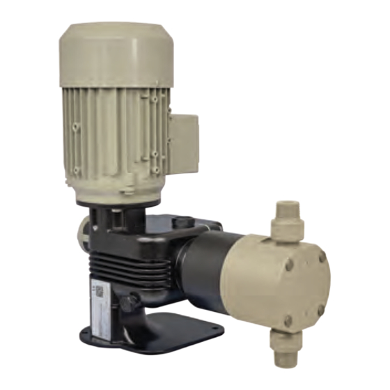
Page 7: Fig. 1. Prius P Pump
Fig. 1. PRIUS P pump Stroke lenght knob... -
Page 8: Features
1.3 Features Power supply ..............220-240/380-420 V - 50 Hz 3-PHASE ..................220/380 V - 60 Hz 3-PHASE Aluminium enclosure (epoxy coating) Ceramic (SIALOX96 ) or stainless steel (AISI420) plunger Environment temperature: -10 ÷ 40°C (14 ÷ 104°F) Chemical temperature with SS pump head: -10 ÷ 90°C (14 ÷ 194°F)* Chemical temperature with PP pump head: -10 ÷... -
Page 9: Plunger
1.3.1 PLUNGER Prius P plunger pumps. Material: ceramic (SIALOX96) or Stainless Steel (AISI420) Lenghts available: 14, 25, 32, 40, 50. - Page 10 Tab. 8. PRIUS P - PP pump head PRIUS P 50 Hz HOSES PLUNGER Pressure Capacity INSTALLATION CONNECTION stroke length PRIUS P 50 Hz Stroke/1’ Motor diam. (mm) 010024 010013 G1/2" 0,18 kW 12x18 010010 010005 010080 010043 G1/2" 0,18 kW...
- Page 11 Tab. 9. PRIUS P - SS pump head PRIUS P 50 Hz HOSES PLUNGER Pressure Capacity CONNECTION stroke length PRIUS P 50 Hz Stroke/1’ Motor diam. (mm) 010024 010013 0,18 kW R1/2” 010010 010005 010080 010043 0,18 kW R1/2” 010032...
- Page 12 PRIUS P WITH PP PUMP HEAD AND CERAMIC PLUNGER 60 HZ / 3-PHASE MOTOR PRIUS P 60 Hz HOSES PLUNGER Pressure Capacity INSTALLATION CONNECTION stroke length PRIUS P 60 Hz Stroke/1’ Motor diam. (mm) 010023 G1/2" 010011 0,18 kW 12x18...
-
Page 13: Installation
2. INSTALLATION 2.1 Installation Before start installation, the operator must be aware of safety precautions to prevent physical injury. warnings OPERATOR PROTECTION Use safety equipment according to the company regulations. Use this safety equipment within the work area during installation, service and when handling chemicals: •... -
Page 14: Commissioning Steps
5 steps of installation procedure: Commissioning Pump location steps Oil filling Piping connection Electric wiring Start-up Pump must be installed on a flat base at max 3 m height from tank’s bottom. 2.2.1 Pump location Fasten the pump by clamping screws. Injection point must be higher of tank to avoid accidental chemical injection. -
Page 15: Pump Head
2.2.3 Piping Never operate any pumping system with a blocked suction and discharge. Operation, connection even for a brief period under these conditions, can cause motor to overheat. You must take all necessary measures to avoid this condition. Suction piping should be as short as possible and installed in vertical position to avoid air bubbles suction. -
Page 16: Installation Drawings
2.2.6 Installation Fig. 3. Installation drawings drawings... -
Page 17: Electrical Wiring
3. ELECTRICAL WIRING 3.1 Preliminary The electrical wirings should be carried out by AUTHORIZED AND QUALIFIED checks PERSONNEL only in accordance with local regulations. Before to proceed, verify the following steps: Verify the data on nameplate. Make sure that the electrical data on the nameplate of the motor corresponds to the electrical supply. - Page 18 CONNECTION DIAGRAMS for 1∼PHASE MOTOR MOTOR SUITABLE FOR INSERTIONS WITH RANGE OF AT LEAST 6” INTERVAL...
-
Page 19: Start Up
4. START UP 4.1 Start up All operation before described must be carried out before starting the pump. Pump location Oil filling Piping connection Electric wiring Follow the “GENERAL SAFETY GUIDELINES” PAGE 4. Start the pump at minimum pressure. Turn the stroke lenght knob on 20%. After 5 minutes, gradually increase the capacity until reaching the prescribed value for the operating condition. -
Page 20: Priming
5. PRIMING 5.1 Warnings The first time and where use of the pump is suspended for a long period of time, priming may be necessary. It allows suction piping and pump head to fill with liquid before pumping against pressure. Priming the pump is also recommended when there is air into pump head or into suction pipe. -
Page 21: Maintenance
6. MAINTENANCE 6.1 Maintenance Before start maitenance, the operator must be aware of safety precautions to prevent physical injury. schedule OPERATOR PROTECTION Use safety equipment according to the company regulations. Use this safety equipment within the work area during installation, service and when handling chemicals: •... -
Page 22: Shutdown
• Check the pump capacity (as per nameplate). • Check the pump pressure (as per nameplate). • Check the pump power (as per nameplate). • Change the oil every year (8.000-10.000 operating hours). • Change the oil more often if there are adverse conditions If the pump performance does not satisfy your process requirements, and the process requirements have not changed, then perform these steps: 1. -
Page 23: Troubleshooting
7. TROUBLESHOOTING Tab. 11. Guide to troubleshooting. PROBLEM CAUSE REMEDY Suction valve leaking or blocked Clean or replace suction valve Suction pipe leaking or blocked Replace suction pipe Air bubbles into pump head or into suction Prime the pump as described in “5.1 How Dosing pump not delivering pipe to prime the pump”... -
Page 24: Compatibility Table
8. COMPATIBILITY TABLE 8.1 Chemical Metering pumps are widely used to dose chemical fluids and it is important that the most suitable compatibility material in contact with fluid is selected for each application. This compatibility table serves as a table useful help in this respect. - Page 25 9. DIMENSIONS 157.00 303.00 400.00 187.00 Progettato da: Controllato da: Data: Peso Lordo: Peso Netto: Toll. Gen.
- Page 27 PRODUCT SERVICE REPAIR FORM ENCLOSE THE PRESENT FORM TO THE DELIVERY NOTE DATE ..........SENDER Company name ............................Address ..............................Phone no..............................Contact person............................. PRODUCT TYPE (see product label) DEVICE CODE .............................. S/N (serial number)............................OPERATING CONDITIONS Location/installation description ........................................................
- Page 28 Disposal of end-of-life equipment by users This symbol warns you not to dispose of the product with normal waste. Respect human health and the environment by giving the discarded equipment to a designated collection center for the recycling of electronic and electrical equipment. For more information visit the online site.
Need help?
Do you have a question about the PRIUS P and is the answer not in the manual?
Questions and answers