
Related Manuals for Emec AMS Series


Summary of Contents for Emec AMS Series
- Page 1 AMS - AMSA - AMS AC PRODUCT LABEL AMSA AMS AC SOLENOID DRIVEN METERING PUMPS WITH DIAPHRAGM...
-
Page 2: General Safety Guidelines
This operating instructions contains safety information that if ignored can endanger life or result in serious injury. Read these instructions carefully before use and keep them for future reference. The original instruction is in Italian. All non-Italian instructions are translations of the original instruction. Information and specifications on this manual could be uncorrect or could have printing errors. - Page 3 pURpOSE Of USE AND METERING pUMp IS INTENDED fOR ChEMICAL DOSING AND DRINkING WATER SAfETY TREATMENT. Do not use in explosive area (EX). Do not use with flammable chemicals. Do not use with radioactive chemicals. Use after a proper installation. Use the pump in accordance with the data and specifications printed on the label.
-
Page 4: Environmental Safety
ENvIRONMENTAL Work area SAfETY Always keep the pump area clean to avoid and/or discover emissions. Recycling guidelines EWC code: 16 02 14 Always recycle according to these guidelines: 1. If the unit or parts are accepted by an authorized recycling company, then follow local recycling laws and regulations. - Page 5 Transportation and A not suitable transportation or storage can cause damages. storage Use origianal box to pack the pump. Observe storage conditions also for transportation. Although packed, always protect the unit against humidity and the action of chemicals. Before return the dosing pump to the manufacturer Repair service, drain the chemical ⎘...
- Page 6 1. Introduction 1.1 AMS Series AMS metering pumps are the ideal solution for low / middle dosing of chemicals. Flow rate is determined by the stroke length and by the stroke speed. The stroke length is adjustable from 0 to 100% using the stroke length adjustment knob.
- Page 7 2. Unpacking Included into package: Dibbles ø6 Self tapping screws 4,5 x 40 Delayed fuse 5 X 20 Level probe with axial foot filter (PVDF) - not present in “CO” models Injection valve Delivery pipe (PVDF) Suction pipe (transparent PVC) Venting pipe (transparent PVC) This installation manual If hose is 6x8 there is only a 4 meters long hose.
-
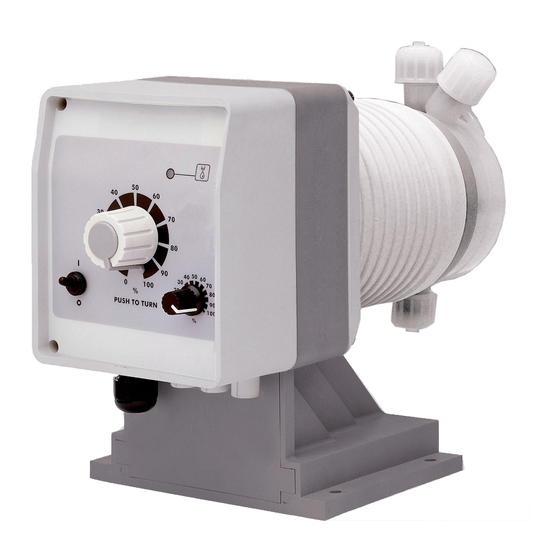
Page 8: Pump's Description
3. pump’s description Fig. 3. AMS - AMSA dosing pumps L.E.D. pulse ON/OFF switch RED THREADING Manual stroke length adjustment ⎘ Construction Materials and Technical info) Max cc/stroke ( are referred to cc/stroke with stroke length knob on 100%. The stroke length knob adjusts the pump capacity. Press and rotate the knob when the pump is powered. - Page 9 AMS AC pumps Compressed air without lubrifiant and/or condensed water. Air supply pressure range must be from 6 to 10 bar.
-
Page 10: Before To Install Warnings
4. Before to Install warnings Pump’s installation and operativity is made in 4 main steps: Pump’s installation Hydraulic Installation (hoses, level probe, injection valve) Electrical Installation (main power connection, priming) Programming the pump. Before to start, please read carefully the following safety information. pROTECTIvE CLOThES Wear always protective clothes as masks, gloves, safety glasses, ear plugs or ear muffs, and further security devices during ALL installation procedure and... -
Page 11: Installation Draw
5. Installation draw Pump must be installed in a stable support (for example a table) at a maximum height (from tank’s bottom) of 1,5 meters. 1 - Dosing Pump 2 - Suction Hose 3 - Delivery Hose 4 - Injection Valve 5 - Air discharge 6 - Level Probe 7 - Foot Filter... -
Page 12: Hydraulic Installation
6. hydraulic installation Hydraulic connections are: Suction Hose with level probe and foot filter Delivery Hose with injection valve Venting hose Suction hose. Completely unscrew tightening nut from pump’s head and remove assembling components: tightening nut, holding ring and pipe holder. Assembly as shown in fig. - Page 13 Assembling foot filter with level probe (not present in CO models). Level probe must be assembled with foot filter using the provided kit. Foot valve is made to be installed into tank’s bottom without sediments priming problem. STEP 5 STEP 4 INSERT RING AS SHOWN STEP 3 INSERT PROBE...
-
Page 14: Injection Valve
Injection valve. Injection valve must be installed on plant from water’s input. Injection valve will open at pressure greater than 0,3 bar. venting hose. Insert one side of venting hose into venting connector as shown in fig (C). Insert other side of venting hose into product’s tank. During priming procedure product exceeding will flow into tank. - Page 15 6. hydraulic Installation 7. Self-venting pump head installation Self-venting pump head must be used when using chemicals that produce gas (i.e. hydrogen peroxide, ammonium, sodium hypoclorite at particular conditions). Refer to fig. 4-5 for delivery and venting hose. Hoses assembling procedures are the same described before. Fig.
-
Page 16: Electrical Installation
8. Electrical Installation All electrical connections must be performed by AUThORIZED AND qUALIfIED personnel only. Before to proceed, please, verify the following steps: - verify that pump’s label values are compatible with main power supply. - pump must be connected to a plant with a differential switch (0,03A sensitivity) if there isn’t a good ground. - Page 17 Once verified previous steps proceed as follows: - check that “BNC” of level probe has been connected as described in “Hydraulic Installation” chapter. - connect “BNC” and external signal to pump’s “INPUT” connectors. Level input Power supply Input OR Water meter input Only for AMS IC;...
-
Page 18: Level Alarm
9. Level alarm - Models LEvEL ALARM CL, IS, IC, PV and TE type pump are provided with a liquid level alarm to indicate if product tank is empty. The level probe is connected to the right BNC plug on pump’s bottom panel. The level probe is made of a N.O. reed contact (10VA, 1A max, 230Vac max) closed by a floating magnet housed in a (PP) plastic box. - Page 19 AMS IS Proportional/constant pump driven by a digital signal. Setting the switch on the constant position, the pump has the same features and adjustments of the CL pump. Setting the switch on the proportional position, to each external voltage free pulse correspond a magnet stroke. When proportional position is set, the % marked knob does NOT affect the pump capacity.
- Page 20 pump model cc max piston displacement AMS PV 2505 0,70 100% AMS PV 1510 100% AMS PV 1015 2,08 100% AMS PV 0720 100% AMS PV 0340 100% AMS PV 0260 100% If the dividing factor (N), obtained with the above formula, is <1, a pump with higher single stroke dosing quantity is required or the water meter needs to be changed with one that gives higher number of pulses per liter.
- Page 21 10. priming pRIMING To prime the pump without touching chemicals please do as follow: - connect all hoses into proper places (delivery hose, suction hose, outgassing hose). - open outgassing valve and turn on the pump. - set pump’s single injection at 100% and pulses at 50%. All air inside the pump head will exit through the outgassing outlet.
-
Page 22: Troubleshooting
11. Troubleshooting problem possible Cause Pump isn’t powered. Connect it to main supply. Pump’s protection fuse is broken. Replace it. See page 19 for pump doesn’t turn on. replacement procedure. Pump’s main board is broken. Replace it. See page 19 for replacement procedure. -
Page 23: Fuse And Main Board Replacement
12. fuse and main board replacement Fuse or main board replacement is allowed to qualified personnel only. Before to operate disconnect the pump from main power and all hydraulic connections. For fuse replacement is necessary to use a 3x16 and 3x15 screwdriver and a new fuse (same model of old one). For main board replacement is necessary to use a 3x16 and 3x15 screwdriver and a new main board (same model of old one). -
Page 24: Main Board
13. Main Board 230/115 VAC 230/115 VAC + Level Solenoid Solenoid Power supply Power supply Level probe switch input (- Level) “CO” power “CL” power Circuit Board Circuit Board 230/115 VAC 230/115 VAC + Level + Level Solenoid Solenoid Power supply Power supply External Pulse or Water meter... -
Page 25: A Appendix. Maintenance
A Appendix. Maintenance In order to ensure the requirements of potable drinking water treated and the Maintenance schedule maintenance of the improvements as declared by the manufacturer, this equipment must be checked at least once a month. OpERATOR pROTECTION Use safety equipment according to the company regulations. Use this safety equipment within the work area during installation, service and when handling chemicals: •... - Page 26 f the pump performance does not satisfy your process requirements, and the process requirements have not changed, then perform these steps: 1. Disassemble the pump. 2. Inspect it. 3. Replace worn parts. This procedure ShOULD BE CARRIED OUT BY AUThORIZED AND qUALIfIED Shutdown procedure pERSONNEL...
-
Page 27: B Appendix. Construction Materials And Technical Info
B Appendix. Construction Materials and Technical info POWER SUPPLY FREQ. FUSE 230 VAC (180-270 VAC) 50/60 Hz 1,25 A 115 VAC (90-135 VAC) 50/60 Hz 1,6 A 24 VAC (20-32 VAC) 50/60 Hz 6,3 A 12 VDC (10-16 VDC) Injection/min 0 ÷... - Page 28 INfORMATION Ampere peak cc per flow pressure stroke pvDf Models stroke/ Suction pump Delivery hose head hose cc/h 2505 0,039 1.32 0,21 0.70 4 x 6 4x 6 1510 0,079 2.64 0,42 4 x 6 4 x 6 1015 0,118 3.96 0.62 2.08...
-
Page 29: C Appendix. Delivery Curves
C Appendix. Delivery Curves Pump head L Pump head M 25 - 05 15 - 10 l/h 05 l/h 10 bar 25 bar 15 Pump head M Pump head N 10 - 15 07 - 20 l/h 15 l/h 20 bar 10 bar 07 Pump head S... -
Page 30: C Appendix. Delivery Curves For Self-Purge Pump Head
C Appendix. Delivery Curves for self-purge pump head Pump head LA Pump head MA 25 - 3,2 15 - 06 l/h 2,3 l/h 06 bar 25 bar 15 Pump head NA 07- 13 Flow rate indicated is for H O at 20°C at the rated pressure. -
Page 31: D Appendix. Dimensions
D Appendix. Dimensions 87.00 152.60 154.80 127.00 265.70 283.20 Progettato da Controllato da Modificato da, Massimo_F 87.00 152.60 127.00 154.80 278.20 295.70 Progettato da Data Controllato da Modificato da, il Massimo_F 27/01/2010 Materiale: Edizione Dimensionale-CMS_Cp_S-T... -
Page 32: E Appendix. Chemical Compatibility Table
E Appendix. Chemical Compatibility Table Solenoid driven metering pumps are widely used to dose chemical fluids and it is important that the most suitable material in contact with fluid is selected for each application. This compatibility table serves as a useful help in this respect. All the informations in this list are verified periodically and believed to be correct on the date of issuance. - Page 33 f Appendix. hoses resistance table Hose features are very important for a reliable dosage. Every pump’s model is made to work in the best way using selected hoses according to pump’s capacity / model. Information reported here are intended for standard use only. For extended information ask to hose’s manufacturer.
- Page 34 G Appendix. Installation draw for AMS CO 1) Injection Valve 2) Venting hose 3) Safety switch 4) Control Panel 5) Mains cable 6) Out gassing hose 7) Suction Hose 8) Foot valve filter...
- Page 35 h Appendix. Installation draw for AMS CL 1) Injection Valve 2) Venting hose 3) Safety switch 4) Control Panel 5) Mains cable 6) Out gassing hose 7) Suction Hose 8) Foot valve filter 9) Level Probe Switch...
- Page 36 I Appendix. Installation draw for AMS IS 1) Injection Valve 2) Venting hose 3) Safety switch 4) Control Panel 5) Mains cable 6) Out gassing hose 7) Suction Hose 8) Foot valve filter 9) Level Probe Switch 10) CCS computerised controller 11) External digital signal input...
- Page 37 L Appendix. Installation draw for AMS pv 1) Injection Valve 2) Venting hose 3) Safety switch 4) Control Panel 5) Mains cable 6) Out gassing hose 7) Suction Hose 8) Foot valve filter 9) Level Probe Switch 10) Pulse emitting water meter...
-
Page 38: Exploded View
M. Exploded view NOTICE: always specify the pump’s label when ordering spare parts. AMS - AMSA... - Page 39 AMS AC...
- Page 40 MOD 7.5 B1 Q Ed. 1 - rev. 0 21/02/2012 pRODUCT SERvICE REpAIR fORM ENCLOSE THE PRESENT FORM TO THE DELIVERY NOTE DATE ..........SENDER Company name ............................Address ..............................Phone no..............................Contact person............................. pRODUCT TYpE (see product label) DEVICE CODE ..............................
- Page 43 Index GENERAL SAFETY GUIDELINES ..............2 PURPOSE OF USE AND SAFETY ..............3 ENVIRONMENTAL SAFETY .................4 LABELS .....................4 SPARE PARTS ....................4 1. Introduction ..................6 2. Unpacking .....................7 3. Pump’s description ................8 4. Before to Install warnings ..............10 5. Installation draw ...................11 6. Hydraulic installation ................12 7.
- Page 44 When dismantling a pump please separate material types and send them according to local recycling disposal requirements. We appreciate your efforts in supporting your local Recycle Environmental Program. Working together we’ll form an active union to assure the world’s invaluable resources are conserved.
Need help?
Do you have a question about the AMS Series and is the answer not in the manual?
Questions and answers