Table of Contents
Advertisement
Quick Links
Installation and User manual
534.02.546/ HH-772GS
534.02.526/ HH-773GS
HÄFELE VINA JSC HEAD OFFICE
Hafele (Thailand) Limited.
Ree Tower, 3rd Floor,
9 Doan Van Bo, District 4,
57 Soi Sukhumvit 64, Sukhumvit Rd., Bangchak, Phrakanong, Bangkok 10260
Ho Chi Minh City, Vietnam.
Telephone: (02) 741-7171
Tel: +84 8 39113113
Fax: +84 8 39113114
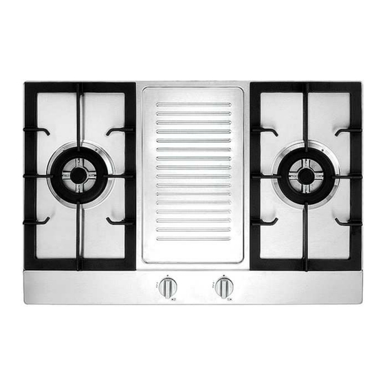
Built in gas hob
534.02.547/ HH-772GG
534.02.527/ HH-773GG
Advertisement
Table of Contents

Related Manuals for Häfele HH-772GG


Summary of Contents for Häfele HH-772GG
- Page 1 Installation and User manual Built in gas hob 534.02.546/ HH-772GS 534.02.547/ HH-772GG 534.02.527/ HH-773GG 534.02.526/ HH-773GS HÄFELE VINA JSC HEAD OFFICE Hafele (Thailand) Limited. Ree Tower, 3rd Floor, 9 Doan Van Bo, District 4, 57 Soi Sukhumvit 64, Sukhumvit Rd., Bangchak, Phrakanong, Bangkok 10260 Ho Chi Minh City, Vietnam.
-
Page 2: For The User For Your Safety
These instructions have been drawn up for your safety and that of others. You are therefore requested to read them carefully before installing and using the appliance. Keep this instruction manual for future reference as necessary. If the appliance is sold or moved, make sure that the manual is handed over to the new user. - Page 3 During use This product is designed to cook food inside ordinary homes and for • non-professional purposes. It should not be used for any other purpose. After using the appliance, make sure that all controls are in “CLOSED” or • “OFF”...
-
Page 4: Table Of Contents
Environmental protection advice All the materials used are environmentally compatible and recyclable. Please • make your contribution to conserving the environment by using the separate waste collection channels available. Decommissioned appliances Appliances which are no longer used or usable are not worthless waste. •... -
Page 5: Description Of The Hob
Guide to reading the instructions The following symbols will help you When reading the instructions: Safety information “Step by step” instructions Suggestions and Advice Information concerning environmental protection This appliance complies with the following EEC Directives: 73/23 and 90/683 (relating to Low Voltage); 89/336 (relating to Electromagnetic Compatibility);... -
Page 6: Instructions For Use
Instructions for use The hob control knobs The symbols on the control knobs mean the following: ● no gas flow maximum gas flow Minimum gas flow All operating positions must be set between the maximum and minimum flow settings, and never between the maximum setting and the closed position. - Page 7 Lighting the burners To obtain a flame more easily, light the burner before placing a cooking utensil on the pan stand To light a burner, proceed as follow: for Version with lighting integrated in the control knob push the knob of the burner fully down and turn it anticlockwise to the “maximum flow”...
-
Page 8: Cleaning And Maintenance
Cleaning and maintenance Before each operation, disconnect the appliance from the electrical mains and allow it to cool down. General cleaning Wash enameled parts with lukewarm water and detergent: do not use abrasive products which might damage them. Wash the flame caps and burner caps often with boiling water and detergent, taking care to remove all deposits The hob pan stands can also be washed in a dishwasher For stubborn dirt, use ordinary non-abrasive detergents or specific commercial... - Page 9 Routine maintenance Have the condition and efficiency of the gas pipe and the pressure regulator (if installed) checked periodically. If anomalies are found, do not repairs but have the faulty part replaced. To ensure good performance and safety, the gas regulator taps must be greased periodically.
-
Page 10: Technical Data
Technical Data Dimensions in mm: Installation opening L x P 1. 550 x 470 2. 550 x 470 3. 750 x 470 OUTPU OUTPU 20mbar 28-30mbar 50mbar BURNER Nozzl Nozzle Nozzle TYPE Makin Cons Makin Makin Small Auxiliary 1.00 0.35 0.72 0.095 0.50... -
Page 11: Instructions For The Installation Technician
Instructions for the installation technician CAUTION: This appliance must only be installed and used in rooms with permanent ventilation to local standards. Installation of the appliance and its connection to the electrical mains must only be carried out by QUALIFIED PERSONEL. Before any procedure, it is important to check that the appliance is DISCONNECTED from the electrical mains. - Page 12 Discharge of flue gases Gas cooking appliances must discharge their flue gases through hoods connected directly to flues or the outdoors. If it is not possible to install the hood (fig. B) an electric fan must be installed on the outside wall or the window of the room, provided it is possible for the ventilation opening to be increased in proportion to the delivery rate of the fan (fig.
-
Page 13: Electrical Connection
Connection Make the connection to the gas system using a rigid metal pipe and regulation unions, or with a stainless steel hose complying with the local standard. If metal hoses are used, take care that they do not come into contact with mobile parts and are not crushed. -
Page 14: Adapting To The Different Types Of Gas
yellow/green earth wire. The brown live wire (connected to the “L” terminal of the terminal board) must always be connected to the live wire of the power supply mains. In all cases, the power supply lead must be positioned so that it does not reach a temperature 50 C above the room temperature at any point. -
Page 15: Building Into Fitted Kitchen Units
Setting the minimum level 1) Light the burner as already described. 2) Turn the tap to the minimum flame position. 3) Remove the control knobs. 4) Use a thin straight screwdriver to turn the by-pass pin located next to the tap rod (see fig. B).For LPG, turn the by-pass pin fully clockwise. - Page 16 These hobs are designed for installation in fitted kitchen units up to 600mm deep with suitable characteristics. Any cabinet side panels taller than the height of the hob itself must be at least 150mm away from the opening into which the hob is inserted. The dimensions of the hob and the installation opening are shown in the illustration.
- Page 17 Installation options On base cabinet with door When constructing the cabinet, suitable precautions must be taken to prevent contact with the casing of the hob, which becomes very hot during operation. The recommended method for overcoming this problem is illustrated in fig.1 The panel underneath the hob must be easily removable to allow the hob to be locked in position and released in case of servicing work...
- Page 18 Hobs technical specification: Nozzle Making BURNER TYPE input input Gas consumption ( mm ) G20:0.43m3/h 4-Φ0.72+Φ0.81 Triple flame burner G25:0.50 m3/h G20-20 G20:0.29m3/h Mbar Φ1.23 Large rapid burner G25:0.33 m3/h Medium semi-rapid G20:0.19m3/h G25-25 Φ0.98 0.55 burner G25:0.22 m3/h mbar Small Auxiliary G20:0.10 m3/h Φ0.72...
- Page 19 80cm series: 534.02.546/ HH-772GS 534.02.526/ HH-773GS Glass panel 80cm series: 534.02.547/ HH-772GG 534.02.527/ HH-773GG Cutting-out size:...
- Page 20 80 cm cutting out Hafele (Thailand) Limited. 57 Soi Sukhumvit 64, Sukhumvit Rd., Bangchak, Phrakanong, Bangkok 10260 Telephone: (02) 741-7171...
Need help?
Do you have a question about the HH-772GG and is the answer not in the manual?
Questions and answers