Table of Contents
Advertisement
Quick Links
TECHNICAL MANUAL
KPDA-26 DVR15
KPDA-35 DVR15
KPDA-52 DVR15
KPDA-71 DVR15
IMPORTANT NOTE:
Read this manual carefully before installing or operating your new air conditioning unit.
Make sure to save this manual for future reference.
KPDA-90 DVR15
KPDA-105 DVR15
KPDA-105 DTR15
KPDA-125 DVR15
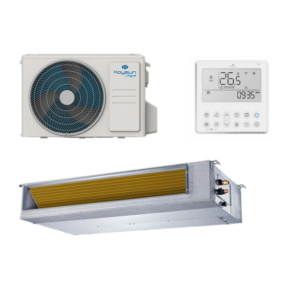
Duct
KPDA-140 DVR15
KPDA-140 DTR15
KPDA-160 DTR15
Advertisement
Table of Contents


Need help?
Do you have a question about the KPDA-26 DVR15 and is the answer not in the manual?
Questions and answers