Table of Contents
Advertisement
Quick Links
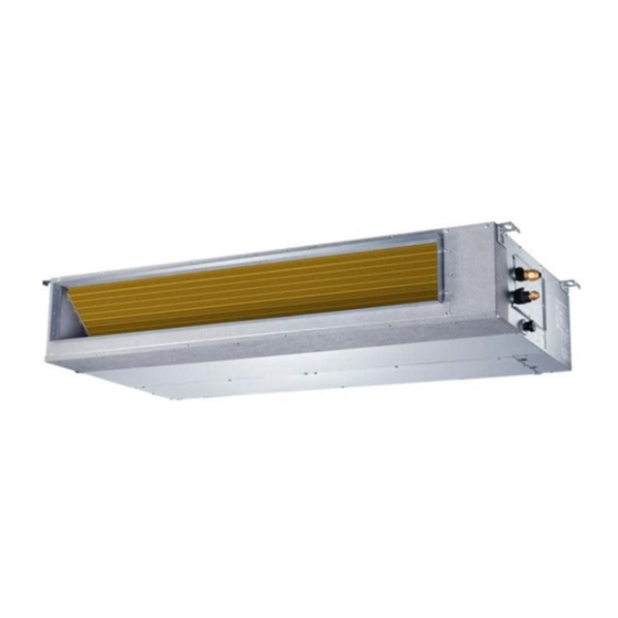
OWNER'S & INSTALLATION
IMPORTANT NOTE:
Read this manual carefully before installing or operating your new air conditioning unit.
Make sure to save this manual for future reference.
Please check the applicable models, technical data, F-GAS(if any) and manufacturer
information from the "Owner's Manual - Product Fiche " in the packaging of the outdoor
unit. (European Union products only)
MANUAL
KPDA-35 DVR14
KPDA-52 DVR14
KPDA-71 DVR14
KPDA-90 DVR14
KPDA-90(140) DVR14
KPDA-105 DVR14
KPDA-105(140) DVR14
KPDA-105 DTR14
KPDA-105(140) DTR14
KPDA-125 DVR14
KPDA-140 DTR14
KPDA-160 DTR14
Duct
Advertisement
Table of Contents


Need help?
Do you have a question about the KPDA-35 DVR14 and is the answer not in the manual?
Questions and answers