Table of Contents
Advertisement
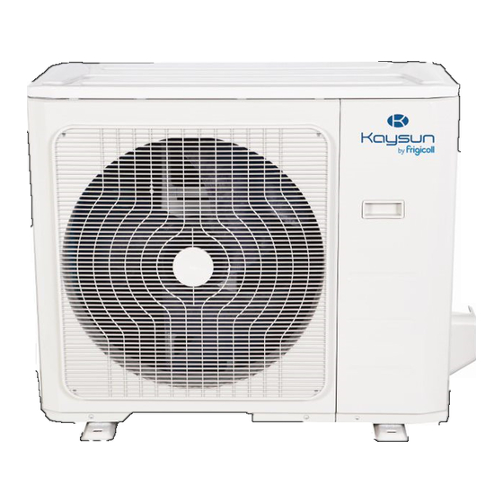
INSTALLATION MANUAL
KPD-35 DVN11
KPD-52 DVN11
KPD-71 DVN11
KPD-90 DVN11
KPD-105 DVN11
IMPORTANT NOTE:
Read this manual carefully before installing or operating your new air conditioning unit. Make sure
to save this manual for future reference.
KPD-105 DTN11
KPD-140 DVN11
KPD-140 DTN11
KPD-160 DTN11
KPD-52 DVR11
A6 Duct
KPD-71 DVR11
KPD-105 DVR11
KPD-105 DTR11
KPD-140 DTR11
KPD-160 DTR11
Advertisement
Table of Contents

Related Manuals for Kaysun KPD-35 DVN11


Summary of Contents for Kaysun KPD-35 DVN11
- Page 1 INSTALLATION MANUAL A6 Duct KPD-35 DVN11 KPD-105 DTN11 KPD-71 DVR11 KPD-52 DVN11 KPD-140 DVN11 KPD-105 DVR11 KPD-71 DVN11 KPD-140 DTN11 KPD-105 DTR11 KPD-90 DVN11 KPD-160 DTN11 KPD-140 DTR11 KPD-105 DVN11 KPD-52 DVR11 KPD-160 DTR11 IMPORTANT NOTE: Read this manual carefully before installing or operating your new air conditioning unit. Make sure...
- Page 2 For R-410 units For R32 units (indoor unit, outdoor unit) ✓ ✗ KPD-35 DVN11 (KPD-35 DR11, KUE-35 DVN11) KPD-52 DVN11 ✓ ✗ (KPD-52 DR11, KUE-52 DVN10) KPD-71 DVN11 ✓ ✗ (KPD-71 DR11, KUE-71 DVN10) KPD-90 DVN11 (KPD-90 DN11, KUE-90 DVN10) ✓...
- Page 3 Table of Contents Installation Manual Accessories ............ Safety Precautions ........Installation Overview ....... Indoor Unit Installation ......a. Indoor Unit Parts ........b. Indoor Unit Installation Instructions ..Outdoor Unit Installation ......a. Outdoor Unit Installation Instructions ..b. Outdoor Unit Types and Specifications..c.
-
Page 4: Table Of Contents
Refrigerant Piping Connection ....A. Notes on Pipe Length and Elevation .... B. Refrigerant Piping Connection Instructions ...21 Wiring ..........a. Outdoor Unit Wiring ....b. Indoor Unit Wiring ....c. Power Specifications ....Air Evacuation ..........a. Evacuation Instructions ........ - Page 5 The air conditioning system comes with the following accessories. Use all the installation parts and accessories to install the air conditioner. Improper installation may result in water leakage, electrical shock and fire, or equipment failure. NAME SHAPE QUANTITY Soundproof / insulation sheath Tubing &...
- Page 6 Read Safety Precautions Before Installation Incorrect installation due to ignoring instructions can cause serious damage or injury. The seriousness of potential damage or injuries is classified as either a WARNING or CAUTION. Failure to observe a warning may result in death. The appliance must be installed in accordance with national regulations.
- Page 7 WARNING • • • Appliance shall be stored in a well-ventilated area where the room size corresponds to the room area as specified for operation. • • Appliance shall be installed, operated and stored in a room with a floor area larger than X m², installation of pipe-work shall be kept to a minimum X m²...
- Page 8 Installation Overview INSTALLATION ORDER Install the outdoor unit Install the drainpipe Install the indoor unit (Page 13) (Page 16) (Page 8) Connect the refrigerant pipes Evacuate the refrigeration system Connect the (Page 27) wires (Page (Page 18) Perform a test run (Page 29)
- Page 9 Indoor Unit Installation Indoor Unit Parts Air inlet Electric control cabinet Air filter (on some models) Drain hose Air outlet Refrigerant connecting pipe Fig. 4.1 Safety Precautions CAUTION WARNING Securely install the indoor unit on a structure • Install the indoor and outdoor units, cables that can sustain its weight.
- Page 10 Step 2: Hang indoor unit. 1. Please refer to the following diagrams to locate the four positioning screw bolt holes on the ceiling. Be sure to mark the places where you will drill ceiling hook holes. Air outlet dimensions Air inlet dimensions Air filter Descending ventilation opening and mounted hook Air filter...
- Page 11 3. Install hanging screw bolts. Wood Cut off the roof beam. Place the wood mounting across the roof beam, Strengthen the point at which the cut was then install the hanging screw bolts. (See Fig.4.4) made. Consolidate the roof beam. 4.
- Page 12 Step 3: Duct and accessories installation 1. Install the filter (optional) according to the size of the air inlet. 2. Install the canvas tie-in between the body and duct. 3. The air inlet and air outlet duct should be far enough apart enough to avoid air passage short-circuit.
- Page 13 Step 5: Fresh air duct installation Step 4: Adjust the air inlet direction (From rear side to under-side.) Dimension: Duct joint for fresh air 1. Take off the ventilation panel and flange. Air return flange MODLE 18-60 Ø125mm(4.92”) Ø160mm (6.3”) Fig.
- Page 14 Outdoor Unit Installation o √ The area must be free of combustible gases Outdoor Unit Installation Instructions and chemicals. The pipe length between the outdoor and o √ Step 1: Select installation location. indoor unit may not exceed the maximum The outdoor unit should be installed in the allowable pipe length.
- Page 15 Split Type Outdoor Unit (Refer to Fig 5.4, 5.5, 5.6, 5.10 and Table 5.1) Fig. 5.4 Fig. 5.5 Fig. 5.6 Table 5.1: Length Specifications of Split Outdoor Unit Dimensions Mounting Dimensions Type Outdoor Unit (unit: mm/inch) W x H x D Distance A Distance B 760x590x285 (29.9x23.2x11.2)
- Page 16 2. Insert the drain joint into the hole in the base NOTE: The minimum distance between the pan of the unit. outdoor unit and walls described in the installation guide does not apply to airtight 3. Rotate the drain joint 90° until it clicks in place rooms.
- Page 17 Drainpipe Installation The drainpipe is used to drain water away from the unit. Improper installation may cause unit NOTE ON DRAINPIPE INSTALLATION and property damage. • When using an extended drainpipe, tighten the indoor connection with an additional CAUTION protection tube. This prevents it from pulling loose.
- Page 18 Units with a pump. 3. Using a 65-mm (2.5”) core drill, drill a hole in the wall. Make sure that the hole is drilled at 1. Remove the test cover. a slight downward angle, so that the outdoor Fill the water pan with 2 liters of water. end of the hole is lower than the indoor end by about 12mm (0.5”).
-
Page 19: Refrigerant Piping Connection
Refrigerant Piping Connection Safety Precautions Notes On Pipe Length and Elevation Ensure that the length of the refrigerant pipe, the number of bends, and the drop height between WARNING the indoor and outdoor units meets the • All field piping must be completed by a requirements shown in Table 7.1: licensed technician and must comply with the local and national regulations. -
Page 20: Refrigerant Piping Connection Instructions
Table 7.2 CAUTION Permitted length DO NOT deform pipe while cutting. Be extra Total piping length 18K+18K 30/98’ L+Max careful not to damage, dent, or deform the pipe (L1, L2) 24K+24K 50/164’ while cutting. This will drastically reduce the heating efficiency of the unit. 30K+30K 1. - Page 21 Clamp flare form on the end of the pipe. The NOTE: Use both a spanner and a torque wrench end of the pipe must extend beyond the when connecting or disconnecting pipes to/from flare form. the unit. Flare form Fig. 7.10 Pipe Fig.
- Page 22 Wiring To prevent distortion when the compressor starts Safety Precautions (you can find the unit’s power information on the rating sticker): WARNING • The unit must be connected to the main outlet. Normally, the power supply must have a impedance of 32 ohms. •...
- Page 23 Indoor Unit Wiring Table 8.1: Other World Regions 1. Prepare the cable for connection. Rated Current of Nominal Cross-Sectional a. Using wire strippers, strip the rubber jacket Appliance (A) Area (mm²) from both ends of the signal cable to reveal £...
- Page 24 CAUTION While connecting the wires, please strictly • - Press “CONFIRM”. The air conditioning follow the wiring diagram. unit will then start the fan for airflow The refrigerant circuit can become very • automatic adjustment. hot. Keep the interconnection cable away from the copper tube.
- Page 25 Power Specifications NOTE: Electric auxiliary heating type circuit breaker/fuse need to add more than 10 A. Indoor Power Supply Specifications £18K MODEL(Btu/h) 19K~24K 25K~36K 37K~48K 49K~60K PHASE 1 Phase 1 Phase 1 Phase 1 Phase 1 Phase POWER 208-240V 208-240V 208-240V 208-240V 208-240V...
- Page 26 £36K £36K MODEL(Btu/h) 37K~60K 37K~60K PHASE 1 Phase 1 Phase 1 Phase 1 Phase POWER (indoor) 208-240V 208-240V 208-240V 208-240V VOLT CIRCUIT BREAKER/FUSE(A) 15/10 15/10 15/10 15/10 PHASE 3 Phase 3 Phase 3 Phase 3 Phase POWER (outdoor) 380-420V 380-420V 208-240V 208-240V VOLT...
-
Page 27: Air Evacuation
Air Evacuation 4. Turn on the vacuum pump to evacuate the Safety Precautions system. 5. Run the vacuum for at least 15 minutes, or until the Compound Meter reads -76cmHG CAUTION (-1x10⁵Pa). 6. Close the manifold gauge’s Low-Pressure valve and turn off the vacuum pump. 7. -
Page 28: Note On Adding Refrigerant
Note On Adding Refrigerant CAUTION • Refrigerant charging must be performed after wiring, vacuuming, and the leak testing. DO NOT exceed the maximum allowable quantity of refrigerant or overcharge the system. • Doing so can damage the unit or impact it’s functioning. •... -
Page 29: Test Run
f. Check to see that the drainage system is Before Test Run unimpeded and draining smoothly. A test run must be performed after the entire g. Ensure there is no vibration or abnormal system has been completely installed. Confirm noise during operation. the following points before performing the test: 5. - Page 30 Users in European Countries may be required to properly dispose of this unit. This appliance contains refrigerant and other potentially hazardous materials. When disposing of this appliance, the law requires special collection and treatment. DO NOT dispose of this product as household waste or unsorted municipal waste.
-
Page 31: Information Servicing
Information Servicing (Required for the units adopt R32 Refrigerant only) 1. Checks to the area Prior to beginning work on systems containing flammable refrigerants, safety checks are necessary to ensure that the risk of ignition is minimized. For repair to the refrigerating system, the following precautions shall be complied with prior to conducting work on the system. - Page 32 the charge size is in accordance with the room size within which the refrigerant containing parts are installed; the ventilation machinery and outlets are operating adequately and are not obstructed; if an indirect refrigerating circuit is being used, the secondary circuits shall be checked for the presence of refrigerant;...
- Page 33 11. Repair to intrinsically safe components Do not apply any permanent inductive or capacitance loads to the circuit without ensuring that this will not exceed the permissible voltage and current permitted for the equipment in use. Intrinsically safe components are the only types that can be worked on while live in the presence of a flammable atmosphere.
- Page 34 When the final OFN charge is used, the system shall be vented down to atmospheric pressure to enable work to take place. This operation is vital if brazing operations on the pipe-work are to take place. Ensure that the outlet for the vacuum pump is not closed to any ignition sources and there is ventilation available.
- Page 35 18. Labelling Equipment shall be labelled stating that it has been de-commissioned and emptied of refrigerant. The label shall be dated and signed. Ensure that there are labels on the equipment stating the equipment contains flammable refrigerant. 19. Recovery When removing refrigerant from a system, either for service or decommissioning, it is recommended good practice that all refrigerants are removed safely.
- Page 36 (It comes from page 22)
-
Page 37: Additional Installation Guide
Additional Installation Guide 1.3 With Built-in pump (24K, 30K, 36K, 48K, 55K Horizontal Installation models) 1.1 With External pump (12K models) Cut both ends of the rubber connective pipe into a Drain connector A, B & C are covered with caps straight one, use it to connect the drainage outlet originally. - Page 38 2.2 Drain pipe connecting When installed vertically (up flow), the pump must be disabled firstly. Follow the 2.1 (Fig.4) steps to disable the pump. For the unit with external pump (12K and 18K model), the whole pump assembly can be removed.
- Page 39 The design and specifications are subject to change without prior notice for product improvement. Consult with the sales agency or manufacturer for details. QSBPT2I-053AEN(R32)(I) 16123000000852 20170927...
Need help?
Do you have a question about the KPD-35 DVN11 and is the answer not in the manual?
Questions and answers