
Subscribe to Our Youtube Channel
Related Manuals for Sollae Systems CSE-M53


Summary of Contents for Sollae Systems CSE-M53
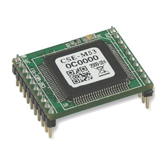
- Page 1 Embedded Serial-Ethernet Converter CSE-M53 User Manual Version 2.4 Sollae Systems Co., Ltd. https://www.ezTCP.com...
- Page 2 CSE-M53 User Manual Ver. 2.4 This symbol, found on your product or on its packaging, indicates that this product should not be treated as household waste when you wish to dispose of it. Instead, it should be handed over to an applicable collection point for the recycling of electrical and electronic equipment.
-
Page 3: Table Of Contents
CSE-M53 User Manual Ver. 2.4 Contents Overview ..........................- 5 - 1.1 Overview ................................- 5 - 1.2 Main Features ..............................- 5 - 1.3 Application Examples ............................- 6 - 1.4 Specification ................................. - 8 - 1.4.1 Hardware ..............................- 8 - 1.4.2 Software ................................ - Page 4 CSE-M53 User Manual Ver. 2.4 Communication Modes ...................... - 28 - 5.1 TCP Server ................................- 28 - 5.1.1 Key parameters ............................- 28 - 5.1.2 Examples ..............................- 29 - 5.2 TCP Client ................................- 32 - 5.2.1 Key parameters ............................- 32 - 5.2.2 Examples ..............................
- Page 5 CSE-M53 User Manual Ver. 2.4 9.2 Warranty ................................- 58 - 9.2.1 Refund ................................. - 58 - 9.2.2 Free Repair Services ..........................- 58 - 9.2.3 Charged Repair Services........................- 58 - Precaution and Exemption from Liability ............... - 59 - 10.1 Precaution................................
-
Page 6: Overview
The serial communication is quite simple to implement but has weaknesses like short distance and hard maintenance. CSE-M53 lets the serial devices connect to the Internet. To communicate on the Internet, devices should use TCP/IP protocol, so CSE-M53 processes the converting serial data to TCP/IP. -
Page 7: Application Examples
CSE-M53 User Manual Ver. 2.4 1.3 Application Examples ⚫ 1:1 Connection with a PC Figure 1-1 1:1 connection with a PC ⚫ Applied to LANs Figure 1-2 applied to LANs - 6 - https://www.ezTCP.com... - Page 8 CSE-M53 User Manual Ver. 2.4 ⚫ Applied to the Internet on Cable Networks Figure 1-3 applied to the Internet on cable networks ⚫ Applied to the Internet with an IP Share Router Figure 1-4 applied to the Internet with an IP share router - 7 - https://www.ezTCP.com...
-
Page 9: Specification
CSE-M53 User Manual Ver. 2.4 1.4 Specification 1.4.1 Hardware Input Voltage DC 3.3V Power Current 160mA typical Dimension 24 mm x 20 mm x 9.1mm Weight About 3.2g RS232 – RTS/CTS and Xon/Xoff Flow Control Serial Port TTL-3.3V Logic Level... -
Page 10: Demension
CSE-M53 User Manual Ver. 2.4 1.4.3 Demension The dimension of CSE-M53 is followed. (Unit: mm) Figure 1-5 dimensions of CSE-M53 - 9 - https://www.ezTCP.com... -
Page 11: Pins
CSE-M53 User Manual Ver. 2.4 1.4.4 Pins ⚫ JP1 / JP2 Connector JP1 and JP2 have headers of 2mm pitch. There is a circle by the first pin (pin number 1) of JP1. Name Description Direction Ground (with a Circle) - Page 12 CSE-M53 User Manual Ver. 2.4 State Wave form In ISP mode In Serial Configuration mode When any IP addresses have not been assigned When IP addresses have been assigned but not connected with a remote host on TCP. - 11 -...
-
Page 13: Voltage Features
CSE-M53 User Manual Ver. 2.4 Connected with a remote host on TCP Table 1-5 STS_LED operation depending on the state 1.4.5 Voltage Features Parameters Description Minimum Typical Maximum Unit Supplied Voltage High-level input voltage Low-level input voltage -0.3 High-level output voltage... -
Page 14: An Application Circuit
CSE-M53 User Manual Ver. 2.4 1.4.6 An Application Circuit 10pF/K 10pF/K 10pF/K 10pF/K Fig 1-1 an Application Circuit - 13 - https://www.ezTCP.com... -
Page 15: Evaluation Board
CSE-M53 User Manual Ver. 2.4 1.5 Evaluation Board Evaluation board for CSE-M53 is equipped a RS45 connector and a D-SUB 9 pin Male connector including the 5V DC power connector. Fig 1-2 EVB for CSE-M53 1.5.1 Parts ① Power Control Jumper: To control supplying the power to the EVB or not. - Page 16 On, when CSE-M53 is available on receiving data CTS (D4) On, when CSE-M53 is available on sending data On, when CSE-M53 is connected with a remote host on TCP Table 1-7 LED Group 1 ⑦ TTL Port: For 3.3V TTL logic level communication ⑧...
-
Page 17: Demension
CSE-M53 User Manual Ver. 2.4 1.5.2 Demension Figure 1-6 Dimension of evaluation board According to conditions of soldering components, the dimensions might be differed with the above figure. Thus, we recommend giving some extra spaces about 1 ~ 2 - 16 - https://www.ezTCP.com... -
Page 18: Installation And Test
Procedures for the test are followed. 2.1.1 Setting Network Aera This step is for setting both CSE-M53 and users’ PC to be located the same network. If only they are, the TCP connection between them can be established. ⚫ Setting of the PC Add or change the IP address of the network adapter on your PC like following. - Page 19 Windows, and this is comfortable to use because it doesn’t need installation. First, search your CSE-M53 via network. All the values of parameters are set the default values in the factory. To apply it to your system, proper values should be set via ezManager.
-
Page 20: Simple Test
⚫ Opening RS232 Port Figure 2-4 opening COM Port ④ Select COM port which the CSE-M53 is connected to ⑤ Make sure that all the parameters are the same with CSE-M53 ⑥ Press the [Open] button - 19 - https://www.ezTCP.com... - Page 21 CSE-M53 User Manual Ver. 2.4 ⚫ Confirm the TCP Connection and COM port status Figure 2-5 TCP Connected message ⑦ Check the message if the TCP connection is established Figure 2-6 COM Port open message ⑧ Check the message if the COM port has been opened - 20 - https://www.ezTCP.com...
- Page 22 CSE-M53 User Manual Ver. 2.4 ⚫ Data transmission test Figure 2-7 successful data transmission ⑨ Click the [Send data] on the LAN part ⑩ Check the data have been shown from the step ⑨ Figure 2-8 LAN → RS232 ⑪ Press the [Send data] on the RS232 part ⑫...
-
Page 23: Configuration
Figure 3-1 initial appearance of ezManager 3.1.1 Configuration via LAN ⚫ Checklists Make sure the connection between your PC and CSE-M53. If they are the same network, [MAC Address search] button can be used. If they aren’t, only [IP Address search] is allowed to use. -
Page 24: Configuration Via Serial
3.1.2 Configuration via Serial ⚫ Checklists Make sure the connection between your PC and CSE-M53 using RS232 cross cable. To use this, CSE-M53 has to be operating in the [Serial Configuration] mode. By connecting ISP- pin with GND (LOW) less than 1 second, you can enter the mode. -
Page 25: At Command
⚫ Checklists Make sure the connection between your PC and CSE-M53 using RS232 cross cable. To use this, CSE-M53 has to be set to [AT command] mode as its communication mode. This can be configured by ezManager. Figure 3-5 setting the communication mode to the AT command ⚫... -
Page 26: Operation Modes
CSE-M53 User Manual Ver. 2.4 Operation Modes 4.1 What is the Operation Mode? Each of three operation mode of CSE-M53 is defined for specific purpose, and those are followed. ⚫ Normal mode This mode is for normal data communication and has 4 different connection modes. -
Page 27: Comparison With Each Mode
CSE-M53 User Manual Ver. 2.4 4.3 Comparison with each mode Table 4-1 shows summaries of each mode Name Entering Serial port Supplying the power when the status of ISP(-) pin Normal changeable is HIGH Serial Giving LOW to the ISP(-) pin between 10ms and 1s... -
Page 28: Serial Configuration Mode
4.6.2 Revoking Serurity Options CSE-M53 offers restriction methods for security like filtering password or MAC and IP address. In the ISP mode, you can revoke all of these. When you forgot the password, enter the ISP mode to solve the problem. -
Page 29: Communication Modes
In this mode, CSE-M53 functions as a TCP server. CSE-M53 listens to a TCP connection from remote host. Once a host tries to connect to CSE-M53, it responses that request. After the connection is established, CSE-M53 converts the raw data from the serial port to TCP/IP data and sends them to the network and vice versa. -
Page 30: Examples
⚫ A situation that [Event Byte] is set to 0. Figure 5-1 time chart for a situation that [Event Byte] is set to zero Points States CSE-M53 is listening to connection requests ① Remote host has sent a connection request (SYN) segment Processes of the connection ②... - Page 31 ⚫ A situation that [Event Byte] is set to 1. Figure 5-2 time chart for a situation that [Event Byte] is set to 1 Points States CSE-M53 is listening to connection requests ① Remote host has sent a connection request (SYN) segment Processes of the connection ②...
- Page 32 Figure 5-3 time chart for a situation that [Timeout] is set to 5 Points States Data communication on both sides ① The last segment has been arrived at the CSE-M53 5 seconds are passed with no data communication CSE-M53 has sent disconnection request (FIN) to a remote ② host Processes of the disconnection ③...
-
Page 33: Tcp Client
CSE-M53 User Manual Ver. 2.4 5.2 TCP Client In this mode, CSE-M53 functions as a TCP client. CSE-M53 sends request segments to a remote host with information of [Peer Address] and [Peer Port]. Once a host is listening and works correctly, the connection will be established. After then, CSE-M53 converts the raw data from the serial port to TCP/IP data and sends them to the network and vice versa. -
Page 34: Examples
CSE-M53 User Manual Ver. 2.4 ⚫ DNS IP Address [DNS IP Address] needs when users use host name instead of the IP address. 5.2.2 Examples ⚫ A situation that [Event Byte] is set to 0. Figure 5-4 time chart for a situation that [Event Byte] is set to 0... - Page 35 The “1234567” is transmitted to the remote host Table 5-8 states of each points As you can see in the figure 5-5, CSE-M53 sends request segment right after the serial data had been 5 bytes. Even though those are come before the connection is established, the data “123”, “45”...
- Page 36 Figure 5-6 time chart for activating [TCP Server] option Points States CSE-M53 is listening to connection requests ① The connection has been established CSE-M53 is on line and processes of the disconnection ② The connection has been terminated Both sides are offline ③ Sends TCP connection request segment Table 5-9 states of each points The TCP Server / Client mode can be useful option by using [Event Byte] and [Timeout].
-
Page 37: At Command
CSE-M53 User Manual Ver. 2.4 5.3 AT Command AT command is a mode which users control CSE-M53 with AT command like controlling modem. In this mode, active and passive TCP connections are available. And users are allowed to configure some environmental parameters with extended commands. -
Page 38: Examples
③ TCP connection has been established CSE-M53 sends “CONNECT” message to the serial port Table 5-11 states of each points Most of the response messages from the serial port of CSE-M53 are omitted on above figure. - 37 -... - Page 39 ⚫ TCP Client – setting parameters and active connection Figure 5-8 TCP Active connection Points States Set parameters in the AT command mode CSE-M53 sends a TCP connection request with the ATD ① command Processes of TCP connection ② TCP connection has been established CSE-M53 sends “CONNECT”...
- Page 40 CSE-M53 sends “NO CARRIER” with disconnection Table 5-13 states of each points CSE-M53 changes the mode to AT command, when receiving “+++” and sending “OK” message. In this state, the communication with remote host is not possible because CSE- M53 processes only AT command. Whenever you want to go back to online state (TCP connection), use “ATO”...
-
Page 41: Udp
CSE-M53 User Manual Ver. 2.4 5.4 UDP UDP has no processes of connection. In this mode, data is sent in block units. Therefore, data that comes through CSE-M53’s serial port must be classified in block units to send it elsewhere. 5.4.1 Key parameters ⚫... -
Page 42: Examples
Figure 5-10 time chart for block size is 5 bytes and data frame is 1s Points States CSE-M53 is receiving data from the serial port CSE-M53 Sends 5 bytes as one block based on the [Block ① Size] Serial device sends data “678” to the CSE-M53 ②... - Page 43 CSE-M53 updates host 2 to peer host CSE-M53 can communicate with remote host 2 Table 5-16 states of each points The data “ABC”, “DE”, “FGH” are from the serial port of CSE-M53 in the above figure. - 42 -...
-
Page 44: System Management
6.1 Upgrading Firmware 6.1.1 Firmware Firmware is a type of software for operation of CSE-M53. If there are needs for adding function or fixing bugs, the firmware is modified and released. We recommend that users keep use the latest released firmware. - Page 45 CSE-M53 User Manual Ver. 2.4 ⚫ Checking firmware file and Sending Figure 6-2 sending firmware file ① Check if the name and path of the firmware file are correct ② Click the [Send] button ③ Confirm the completed message - 44 -...
-
Page 46: Status Monitoring
6.2 Status Monitoring 6.2.1 Using TELNET Once the [TELNET] option is activated, users can remotely log in to CSE-M53. If a password is set, users should input the password. Starting with firmware version 2.0A, you can login by entering "sollae" without ... - Page 47 “st sio” command displays the number of bytes for the serial port. Figure 6-5 “st sio” command ⚫ st uptime “st uptime” command shows amount of time since CSE-M53 boots up. Figure 6-6 “st uptime” command ⚫ sc “sc” command is used when users close a session. [op1] means the name of session, and [op2] should be “close”.
-
Page 48: Using Ezmanager
CSE-M53 User Manual Ver. 2.4 6.2.2 Using ezManager Status of CSE-M53 can be monitored by [Status] button on ezManager. By using the [Refresh Every 1 Second] option in the status window, the status is automatically updated in every second. Figure 6-8 status window of ezManager ⚫... - Page 49 ⚫ Password This text box is activated when CSE-M53 has a password. If users want to close TCP connection with right click of mouse on the session, this password has to be correctly filled.
-
Page 50: Debugging Message
CSE-M53 User Manual Ver. 2.4 6.2.3 Debugging Message By using [Debugging] option, users can receive debugging messages from CSE-M53 on the network. ⚫ Setting debugging option Figure 6-9 setting debugging option ① Check the [Debugging Message] option ② Press the [Write] button ③... - Page 51 Figure 6-10 debugging message window ① Network Adapter ② Place for listing received debugging messages from CSE-M53 over the network ③ Auto update to display the latest captured file on the screen of ② ④ MAC Address and Serial port Information of a selected message ⑤...
- Page 52 CSE-M53 User Manual Ver. 2.4 ⓒ [Reboot] button is for software rebooting ⓓ [Load Message] is for loading a debugging log file to display ⓔ Closing debugging message window If you have problems with communication or connection, it can be helpful for us that ...
-
Page 53: Additional Functions
The maximum length is 8 bytes of Alphabet or number. When you want to revoke all of these restrictions, operate CSE-M53 as ISP mode. In the mode, all restrictions are removable and communication with ezManager is revoked. -
Page 54: Notify Ip Change
CSE-M53 can be TCP server even though it assigned IP address automatically. Using [Notify IP Change] function, CSE-M53 sends its IP address with the host name to the designed server. There are 3 types- DDNS, TCP and UDP- for this service. -
Page 55: Sending Mac Address
CSE-M53 User Manual Ver. 2.4 7.3 Sending MAC Address [Sending MAC Address] is a function that CSE-M53 sends its MAC address to the remote host right after the connection is established. By using this function, a server can identify multiple devices with the information. -
Page 56: Self-Test In Trouble
CSE-M53 User Manual Ver. 2.4 Self-Test in Trouble When users are in trouble with CSE-M53, make sure all the followed steps first. 8.1 Searching problem with ezManager ⚫ Confirming types of configuration utility CSE-M53 can be configured by ezManager. ⚫ Stopping Firewall operation Firewalls of personal computer or network block broadcast packets. -
Page 57: Connection Problem Over Tcp/Ip
Address, Table 8-1 major parameters related with TCP/IP ⚫ PING Test Confirm the connection over the network by PING test. If the CSE-M53 doesn’t send any reply from the request, check the network environment. ⚫ Firewall In case the networks which need strong security, the access may be denied by their firewall. -
Page 58: Data Communication Problem On The Serial
CSE-M53 User Manual Ver. 2.4 8.3 Data Communication Problem on the Serial ⚫ Connection of Pins Check if the connection of each pin is right. Using cables, users choose the right type of cable which is suitable for the device. Transmit Data (TXD) pin should be connected with Receive Data (RXD) pin. -
Page 59: Technical Support And Warranty
Technical Support and Warranty Technical Support If you have any question regarding operation of the product, visit Customer Support FAQ corner and the message board on Sollae Systems’ web site or send us an email at the following address: ⚫ E-mail: support@eztcp.com... -
Page 60: Precaution And Exemption From Liability
CSE-M53 User Manual Ver. 2.4 10 Precaution and Exemption from Liability 10.1 Precaution ⚫ Sollae Systems is not responsible for product failures occurring due to user ’s alternation of the product. ⚫ Specifications of the product are subject to change without prior notice for performance improvement. -
Page 61: Exemption From Liability
(including, without limitation, damages for loss of profit, operating cost for commercial interruption, loss of information, or any other financial loss) from the use or inability to use the CSE-M53 even if Sollae Systems Co., Ltd. Or its distributors have been informed of such damages. -
Page 62: French Version
à caractère commercial ou de toute autre perte financière) provenant de l'utilisation ou de l'incapacité à pouvoir utiliser le boîtier CSE-M53, même si Sollae Systems Co., Ltd ou un de ses distributeurs a été informé de la possibilité de tels dommages. - Page 63 CSE-M53 sans que la responsabilité de Sollae Systems Co., Ltd et de ses distributeurs ne puissent être mise en cause, ni que le boîtier CSE-M5N puisse être échangé au titre de la garantie.
-
Page 64: History
CSE-M53 User Manual Ver. 2.4 11 History Data Version Comments Author 2009.11.05 ○ Created 2009.12.01 ○ The form of History has been changed – Adding Author Roy LEE ○ Description of “sc” command has been changed. ○ Description of debugging message has been changed. - Page 65 CSE-M53 User Manual Ver. 2.4 2024.05.07. ○ Remove the Components chapter Roy LEE ○ Remove the Related Material chapter ○ Update URLs of the website ○ Correct an error on the table 1-9 - 64 - https://www.ezTCP.com...
Need help?
Do you have a question about the CSE-M53 and is the answer not in the manual?
Questions and answers