
Subscribe to Our Youtube Channel
Related Manuals for Sollae Systems CSE-H53


Summary of Contents for Sollae Systems CSE-H53
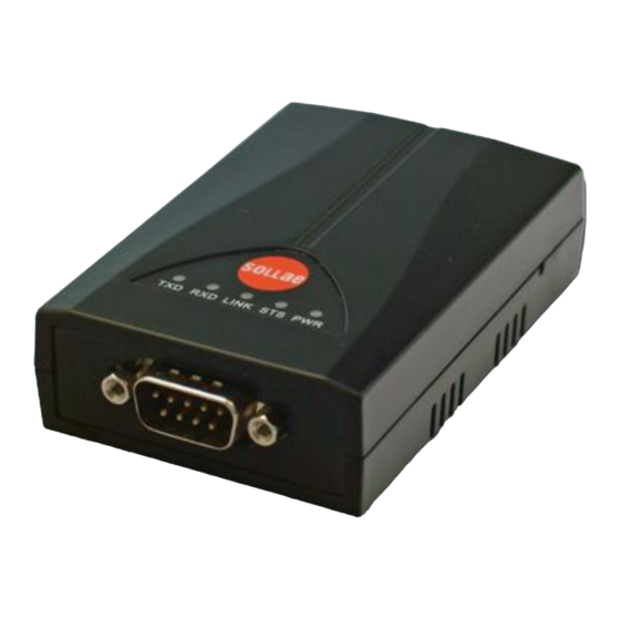
- Page 1 Industrial RS232↔Ethernet Converter CSE-H53 User’s Manual Version 1.7 Sollae Systems Co., Ltd. http://www.ezTCP.com...
- Page 2 CSE-H53 User’s Manual Ver. 1.7 This symbol, found on your product or on its packaging, indicates that this product should not be treated as household waste when you wish to dispose of it. Instead, it should be handed over to an applicable collection point for the recycling of electrical and electronic equipment.
-
Page 3: Table Of Contents
CSE-H53 User’s Manual Ver. 1.7 Contents Overview ..........................- 5 - 1.1 Overview ................................- 5 - 1.2 Main Features ..............................- 5 - 1.3 Application Examples ............................- 6 - 1.4 Components ................................. - 7 - 1.5 Specification ................................. - 8 - 1.5.1 Hardware .............................. - Page 4 CSE-H53 User’s Manual Ver. 1.7 Communication Modes ...................... - 23 - 5.1 TCP Server ................................- 23 - 5.1.1 Key parameters ............................- 23 - 5.1.2 Examples ..............................- 24 - 5.2 TCP Client ................................- 27 - 5.2.1 Key parameters ............................- 27 - 5.2.2 Examples ..............................
- Page 5 CSE-H53 User’s Manual Ver. 1.7 9.2 Smart phone Application ..........................- 53 - Technical Support and Warranty ..................- 54 - 10.1 Technical Support ............................- 54 - 10.2 Warranty ................................- 54 - 10.2.1 Refund ................................. - 54 - 10.2.2 Free Repair Services ..........................
-
Page 6: Overview
The serial communication is quite simple to implement but has weaknesses like short distance and hard maintenance. CSE-H53 lets the serial devices connect to the Internet. To communicate on the Internet, devices should use TCP/IP protocol, so CSE-H53 processes the converting serial data to TCP/IP. -
Page 7: Application Examples
CSE-H53 User’s Manual Ver. 1.7 1.3 Application Examples 1:1 Connection with a PC Fig 1-1 1:1 connection with a PC Applied to LANs Fig 1-2 applied to LANs - 6 - http://www.ezTCP.com... -
Page 8: Components
CSE-H53 User’s Manual Ver. 1.7 Applied to the Internet on Cable Networks Fig 1-3 applied to the Internet on cable networks Applied to the Internet with an IP Share Router Fig 1-4 applied to the Internet with an IP share router 1.4 Components... -
Page 9: Specification
Network Auto MDI or MDIX cable Auto-Sensing Temperature Storage / Operating Temperature: -40 ~ 85℃ Certification CE: F690501/SP-EMY000240 / MIC: SLS-CSE-H53 (A) RoHS RoHS Compliant Table 1-1. Hardware specification 1.5.2 Software TCP, UDP, IP, ICMP, ARP, DHCP, PPPoE, Telnet, DNS Lookup, DDNS,... -
Page 10: Interfaces
CSE-H53 User’s Manual Ver. 1.7 1.6 Interfaces 1.6.1 Serial Interface CSE-H53 has an RS232 port for user serial device (300bps ~ 230,400bps). CSE-H53 converts serial data from user device to TCP/IP and transmits to Ethernet port. Fig 1-5 9 pins D-sub Male connector ... -
Page 11: Ethernet Interface
CSE-H53 User’s Manual Ver. 1.7 1.6.2 Ethernet Interface Since part of CSE-H53 network is composed of Ethernet, UTP cable may be connected. It will automatically sense 10Mbits or 100Mbits Ethernet and connect itself. It also provides auto MDI/MDIX function that can automatically sense 1:1 cable or cross over cable. -
Page 12: System Led
1.7.1 ISP Switch There is a switch, which is named ISP switch (or button) located on the side of the product. You can change the operation mode of CSE-H53 to ISP or Serial Configuration mode with this switch. Fig 1-8 ISP switch - 11 - http://www.ezTCP.com... -
Page 13: Installation And Test
Procedures for the test are followed. 2.1.1 Setting Network Aera This step is for setting both CSE-H53 and users’ PC to be located the same network. If only they are, the TCP connection between them can be established. Setting of the PC Add or change the IP address of the network adapter on your PC like following. - Page 14 Windows, and this is comfortable to use because it doesn’t need installation. First, search your CSE-H53 via network. All the values of parameters are set the default values in the factory. To apply it to your system, proper values should be set via ezManager.
-
Page 15: Simple Test
Opening RS232 Port Fig 2-4 opening COM Port ④ Select COM port which the CSE-H53 is connected to ⑤ Make sure that all the parameters are the same with CSE-H53 ⑥ Press the [Open] button - 14 - http://www.ezTCP.com... - Page 16 CSE-H53 User’s Manual Ver. 1.7 Confirm the TCP Connection and COM port status Fig 2-5 TCP Connected message ⑦ Check the message if the TCP connection is established Fig 2-6 COM Port open message ⑧ Check the message if the COM port has been opened - 15 - http://www.ezTCP.com...
- Page 17 CSE-H53 User’s Manual Ver. 1.7 Data transmission test Fig 2-7 successful data transmission ⑨ Click the [Send data] on the LAN part ⑩ Check the data have been shown from the step ⑨ Fig 2-8 LAN → RS232 ⑪ Press the [Send data] on the RS232 part ⑫...
-
Page 18: Configuration
Fig 3-1 initial appearance of ezManager 3.1.1 Configuration via LAN Checklists Make sure the connection between your PC and CSE-H53. If they are the same network, [MAC Address search] button can be used. If they aren’t, only [IP Address search] is allowed to use. -
Page 19: Configuration Via Serial
3.1.2 Configuration via Serial Checklists Make sure the connection between your PC and CSE-H53 using RS232 cross cable. To use this, CSE-H53 has to be operating in the [Serial Configuration] mode. By pressing the ISP button less than 1 second, you can enter the mode. After this, read the setting via [Serial] tab on ezManager. -
Page 20: At Command
Checklists Make sure the connection between your PC and CSE-H53 using RS232 cross cable. To use this, CSE-H53 has to be set to [AT command] mode as its communication mode. This can be configured by ezManager. Fig 3-5 setting the communication mode to the AT command ... -
Page 21: Operation Modes
CSE-H53 User’s Manual Ver. 1.7 Operation Modes 4.1 What is the Operation Mode? Each of three operation mode of CSE-H53 is defined for specific purpose, and those are followed. Normal mode This mode is for normal data communication and has 4 different connection modes. -
Page 22: Comparison Of Each Mode
CSE-H53 User’s Manual Ver. 1.7 4.3 Comparison of each mode Table 4-1 shows summaries of each mode Name Entering Serial port Configured Normal Supply the power. value Serial Press the ISP button shortly between 10ms and 1s. 115200/N/8/1 Configuration Supply the power with pressing the ISP button or 115200/N/8/1 press the ISP button over 1 sec, in other modes. -
Page 23: Serial Configuration Mode
4.6.2 Revoking Serurity Options CSE-H53 offers restriction methods for security like filtering password or MAC and IP address. In the ISP mode, you can revoke all of these. When you forgot the password, enter the ISP mode to solve the problem. -
Page 24: Communication Modes
In this mode, CSE-H53 functions as a TCP server. CSE-H53 listens to a TCP connection from remote host. Once a host tries to connect to CSE-H53, it responses that request. After the connection is established, CSE-H53 converts the raw data from the serial port to TCP/IP data and sends them to the network and vice versa. -
Page 25: Examples
A situation that [Event Byte] is set to 0. Fig 5-1 time chart for a situation that [Event Byte] is set to zero Points States CSE-H53 is listening to connection requests ① Remote host has sent a connection request (SYN) segment Processes of the connection ②... - Page 26 A situation that [Event Byte] is set to 1. Fig 5-2 time chart for a situation that [Event Byte] is set to 1 Points States CSE-H53 is listening to connection requests ① Remote host has sent a connection request (SYN) segment Processes of the connection ②...
- Page 27 Fig 5-3 time chart for a situation that [Timeout] is set to 5 Points States Data communication on both sides ① The last segment has been arrived at the CSE-H53 5 seconds are passed with no data communication CSE-H53 has sent disconnection request (FIN) to a remote ② host Processes of the disconnection ③...
-
Page 28: Tcp Client
CSE-H53 tries to terminate established TCP connection. TCP Server This check option is enable the TCP server / client mode. In this mode, CSE-H53 can be operated as a TCP server or client without changing its setting. DNS IP Address [DNS IP Address] needs when you use host name instead of the IP address. -
Page 29: Examples
CSE-H53 User’s Manual Ver. 1.7 5.2.2 Examples A situation that [Event Byte] is set to 0. Fig 5-4 time chart for a situation that [Event Byte] is set to 0 Points States Before the power is supplied ① Sends TCP connection request segment right after it boots up Processes of the disconnection ②... - Page 30 The “1234567” is transmitted to the remote host Table 5-8 states of Fig 5-5 As you can see in the figure 5-5, CSE-H53 sends request segment right after the serial data had been 5 bytes. Even though those are come before the connection is established, the data “123”, “45”...
- Page 31 Fig 5-6 time chart for activating [TCP Server] option Points States CSE-H53 is listening to connection requests ① The connection has been established CSE-H53 is on line and processes of the disconnection ② The connection has been terminated Both sides are offline ③ Sends TCP connection request segment Table 5-9 states of Fig 5-6 The TCP Server / Client mode can be useful option by using [Event Byte] and [Timeout].
-
Page 32: At Command
CSE-H53 User’s Manual Ver. 1.7 5.3 AT Command AT command is a mode which users control CSE-H53 with AT command like controlling modem. In this mode, active and passive TCP connections are available. And users are allowed to configure some environmental parameters with extended commands. -
Page 33: Examples
③ TCP connection has been established CSE-H53 sends “CONNECT” message to the serial port Table 5-11 states of Fig 5-7 Most of the response messages from the serial port of CSE-H53 are omitted on above figure. - 32 - http://www.ezTCP.com... - Page 34 TCP Client – setting parameters and active connection Fig 5-8 TCP Active connection Points States Set parameters in the AT command mode CSE-H53 sends a TCP connection request with the ATD ① command Processes of TCP connection ② TCP connection has been established CSE-H53 sends “CONNECT”...
- Page 35 CSE-H53 sends “NO CARRIER” with disconnection Table 5-13 states of Fig 5-9 CSE-H53 changes the mode to AT command, when receiving “+++” and sending “OK” message. In this state, the communication with remote host is not possible because CSE- H53 processes only AT command. Whenever you want to go back to online state (TCP connection), use “ATO”...
-
Page 36: Udp
CSE-H53 User’s Manual Ver. 1.7 5.4 UDP UDP has no processes of connection. In this mode, data is sent in block units. Therefore, data that comes through CSE-H53’s serial port must be classified in block units to send it elsewhere. 5.4.1 Key parameters ... -
Page 37: Examples
Fig 5-10 time chart for event byte is 5 bytes and data frame is 1s Points States CSE-H53 is receiving data from the serial port CSE-H53 Sends 5 bytes as one block based on the [Event ① byte] Serial device sends data “678” to the CSE-H53 ②... - Page 38 CSE-H53 updates host 2 to peer host CSE-H53 can communicate with remote host 2 Table 5-16 states of Fig 5-11 The data “ABC”, “DE”, “FGH” are from the serial port of CSE-H53 in the Fig 5-11. - 37 -...
-
Page 39: System Management
6.1 Upgrading Firmware 6.1.1 Firmware Firmware is a type of software for operation of CSE-H53. If there are needs for adding function or fixing bugs, the firmware is modified and released. We recommend that users keep use the latest released firmware. - Page 40 CSE-H53 User’s Manual Ver. 1.7 Checking firmware file and Sending Fig 6-2 sending firmware file ① Check if the name and path of the firmware file are correct ② Click the [Send] button ③ Confirm the completed message - 39 -...
-
Page 41: Status Monitoring
CSE-H53 User’s Manual Ver. 1.7 6.2 Status Monitoring 6.2.1 Using TELNET Once the [TELNET] option is activated, users can remotely log in to CSE-H53. If a password is set, users should input the password. After then, messages from CSE-H53 appear like Fig 6-3. - Page 42 “st sio” command displays the number of bytes for the serial port. Fig 6-5 “st sio” command st uptime “st uptime” command shows amount of time since CSE-H53 boots up. Fig 6-6 “st uptime” command sc “sc” command is used when users close a session. [OP1] means the name of session, and [OP2] should be “close”.
-
Page 43: Using Ezmanager
CSE-H53 User’s Manual Ver. 1.7 6.2.2 Using ezManager Status of CSE-H53 can be monitored by [Status] button on ezManager. By using the [Refresh Every 1 Second] option in the status window, the status is automatically updated in every second. Fig 6-8 status window of ezManager ... - Page 44 Password This text box is activated when CSE-H53 has a password. If users want to close TCP connection with right click of mouse on the session, this password has to be correctly filled.
-
Page 45: Debugging Message
CSE-H53 User’s Manual Ver. 1.7 6.2.3 Debugging Message By using [Debugging] option, users can receive debugging messages from CSE-H53 on the network. Setting debugging option Fig 6-9 setting debugging option ① Check the [Debugging Message] option ② Press the [Write] button ③... - Page 46 Fig 6-10 debugging message window ① Network Adapter ② Place for listing received debugging messages from CSE-H53 over the network ③ Auto update to display the latest captured file on the screen of ② ④ MAC Address and Serial port Information of a selected message ⑤...
- Page 47 CSE-H53 User’s Manual Ver. 1.7 ⓒ [Reboot] button is for software rebooting ⓓ [Load Message] is for loading a debugging log file to display ⓔ Closing debugging message window If you have problems with communication or connection, it can be helpful for us that ...
-
Page 48: Additional Functions
The maximum length is 8 bytes of Alphabet or number. When you want to revoke all of these restrictions, operate CSE-H53 as ISP mode. In the mode, all restrictions are removable and communication with ezManager is revoked. -
Page 49: Notify Ip Change
CSE-H53 can be TCP server even though it assigned IP address automatically. Using [Notify IP Change] function, CSE-H53 sends its IP address with the host name to the designed server. There are 3 types- DDNS, TCP and UDP- for this service. -
Page 50: Sending Mac Address
CSE-H53 User’s Manual Ver. 1.7 7.3 Sending MAC Address [Sending MAC Address] is a function that CSE-H53 sends its MAC address to the remote host right after the connection is established. By using this function, a server can identify multiple devices with the information. -
Page 51: Self Test In Trouble
CSE-H53 User’s Manual Ver. 1.7 Self Test in Trouble When users are in trouble with CSE-H53, make sure all the followed steps first. 8.1 Searching problem with ezManager Confirming types of configuration utility CSE-H53 can be configured by ezManager. -
Page 52: Connection Problem Over Tcp/Ip
Address, Table 8-1 major parameters related with TCP/IP PING Test Confirm the connection over the network by PING test. If the CSE-H53 doesn’t send any reply from the request, check the network environment. Firewall In case the networks which need strong security, the access may be denied by their firewall. -
Page 53: Data Communication Problem On The Serial
CSE-H53 User’s Manual Ver. 1.7 8.3 Data Communication Problem on the Serial Connection of Pins Check if the connection of each pin is right. Using cables, users choose the right type of cable which is suitable for the device. Transmit Data (TXD) pin should be connected with Receive Data (RXD) pin. -
Page 54: Related Material
CSE-H53 User’s Manual Ver. 1.7 Related Material Technical Documents You can find the technical documents at our website. DataSheet IP Change Notification(DDNS) Sending MAC Address function TCP Server/Client mode Telnet COM Port Control Option etc Smart phone Application ... -
Page 55: Technical Support And Warranty
10 Technical Support and Warranty 10.1 Technical Support If you have any question regarding operation of the product, visit Customer Support FAQ corner and the message board on Sollae Systems’ web site or send us an email at the following address: E-mail: support@eztcp.com... -
Page 56: Precaution And Exemption From Liability
CSE-H53 User’s Manual Ver. 1.7 11 Precaution and Exemption from Liability 11.1 Precaution Sollae Systems is not responsible for product failures occurring due to user ’s alternation of the product. Specifications of the product are subject to change without prior notice for performance improvement. -
Page 57: Exemption From Liability
Sollae Systems Co., Ltd. and its distributors entire liability and your exclusive remedy shall be Sollae Systems Co., Ltd. and its distributors option for the return of the price paid for, or repair, or replacement of the CSE-H53. -
Page 58: French Version
à caractère commercial ou de toute autre perte financière) provenant de l'utilisation ou de l'incapacité à pouvoir utiliser le boîtier CSE-H53, même si Sollae Systems Co., Ltd. ou un de ses distributeurs a été informé de la possibilité de tels dommages. - Page 59 CSE-H53 sans que la responsabilité de Sollae Systems Co., Ltd. et de ses distributeurs ne puissent être mise en cause, ni que le boîtier CSE-H53 puisse être échangé au titre de la garantie.
-
Page 60: History
CSE-H53 User’s Manual Ver. 1.7 12 History Date Version Comments Author 2009.12.01 ○ Created Roy LEE 2009.12.14 ○ The table 4-1 has been changed. Roy LEE 2010.04.12 ○ Figure 3-2, 3-3 and 3-6 have been replaced. Roy LEE 2010.06.25 ○ Maximum value of the [Event Bytes] has been corrected.
Need help?
Do you have a question about the CSE-H53 and is the answer not in the manual?
Questions and answers